Wiring harness design in CATIA V5 - 3D modeling Week 7 Challenge
- Open catia V5 and open a new product file and harness assembly which need to be flattened(Here week 4 challenge assembly) .
- Rename the product file into a 'Flattening Product'.
- Switch to the Electrical Harness Flattening workbench, and select the command called Harness Flattening Parameters.
- In general tab, change the minimum angle distance between them to 15 to 20 degree.
- Keep existing tangent between bundle segment and connector during the flattening step
- Select the Radius of the bundle segment for the Roll radius for Quick roll.
- In drawing tab, type of presentation , for bundle segment :keep single line, for protective covering: double line. and Graphic replacement:For Device-keep 3D projection enabled. Then click on OK and save.
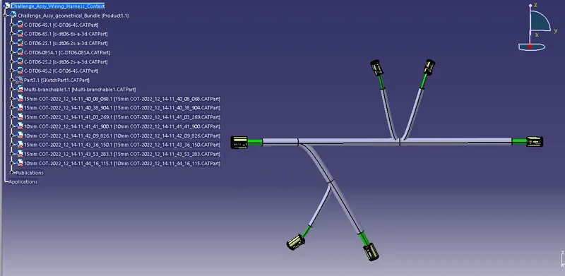
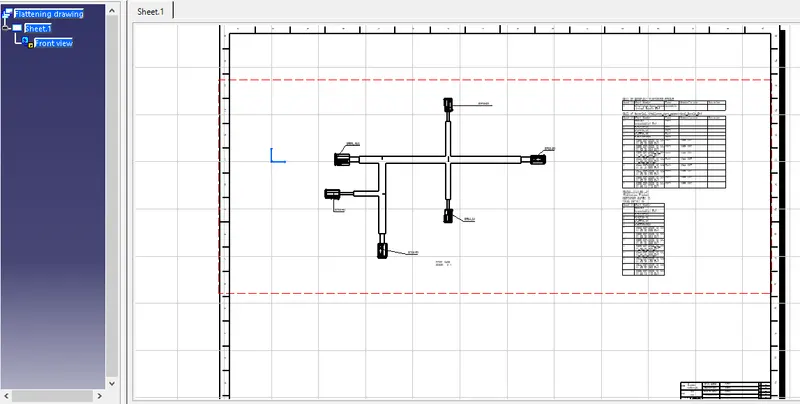
Drawing file with annotations and BOM details.
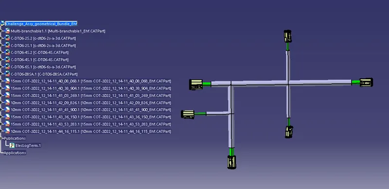
Importing the harness assembly to flattening product file.
- Open the wiring harness assembly file and tile the window vertically.
- Select the Flattening product file in model tree and select the extract command in Electrical Harness Flattening workbench and select the wiring harness assembly file to import the file.
- Now select the Flatten command in Eletrical Harness Flattening Workbench, and in active plane select any plane as a required surface to flatten the harness. and keep algorithm and angle mode default.
- Select one of the branch from the harness aeembly, select all branches command will be activated. Then enable select all branches option. all branches will be selected.Now click on OK.
- Use other commands such as rotate, roll, straighten and synchronization for the alignment of Flattening product as per your requirement.
Creating 2D Harness Flattening Drawing File.
- Open the new drawing file and save as a flattening Drawing File.
- Keep ISO as a standard and A0 ISO as a sheet style.
- And select Landscape.
- Now select the Front view command in Drawing file and select the required surface or the plane for view in the flattening product file which is exact plane used in flattening parameter.
- Now the flatten product details are delivered into the drawing file in a 2D.
- Click right on to drawing , Go to the properties and select the view tab, under dress up section, enable the 3D colors (if needed) and also enable the 3D wireframe is always visible.
- Now the full details of flatten product details are obtained in a 2D form.
- Now the connectors are represented in a 2D. So we can change the representation into 3D by changing the flattening parameters in the flattening product file.
- In flattening product file parameteres, I have used double line for both bundle segment and protective covering double line. We can see Connectors are also represented in 3D view.
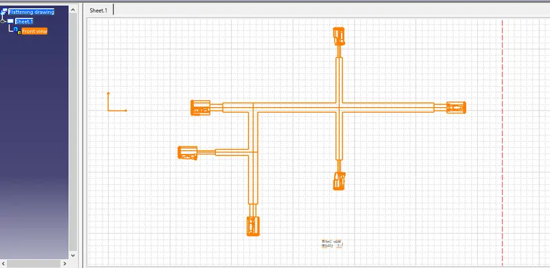
- Drawing file with BOM data and annotation.