Wiring harness design in CATIA V5 - 3D modeling Week 7 Challenge
Aim :
Flatten the harness assembly completed in “ week 4 challenge”.
Objectives :
Place the flattened view on drawing sheet.
Ensure bundles with protective coverings has different visuals on drawing view.
Procedure :
Remebering or Re construct the above given figure :
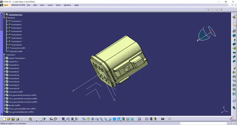
In the Above figure We Have Taken from given source & Merged into Catia V5.
1.Go To the Part design workbench & Taking A middle Point From The Connector Connecting Side As Well As Bundle Connecting Side.
2.Taking the axis Origin of Connector connecting Point.
3.Adusting the y-axis is normal to the face of connector connecting Point & X-axis would be locking side & Z-axis would be Up or down side.
4.Then go to the electrical part design workbench after that defined it as a connector & Add no of terminals it has & defining the connector connection point As well as bundle connection point with respect to their faces & Respresentations.
5.Similarly we have to upload the all connectors.
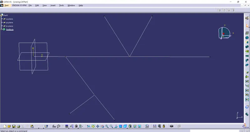
Line Alignment :
Take The line from assembly workbench inn sketch option as per given dimensions we have to constarin the line as shown in figure below.
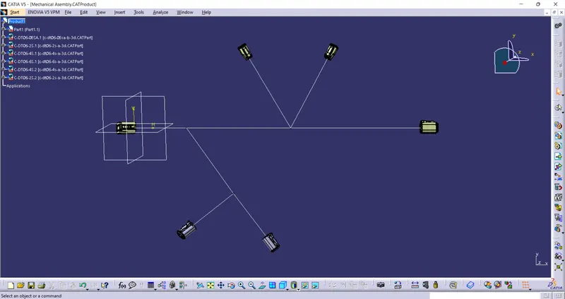
Mechanical Assembly :
now we have to Copy and paste the connectors,line part into the Assembly Workbench.
After that we have to manipulate the connectors according to the given figure then swap into their respective positions as shown in given figure below.
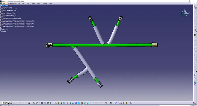
Route the Bundles :
Then Go to the electrical harness Assembly Define the product as an geometric bundle.
Then go the multibranchable point Route the bundles And suiatable break points & add protective coverings with respect to the given Diagram, As shown in figure below.
Placing the flattened view on drawing sheet :
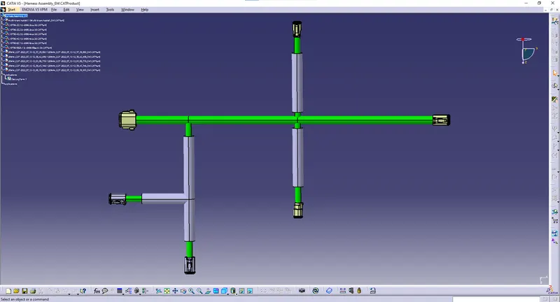
1.open a new electrical falttening product & Give The harness flattening parameters,
& tile vertically & Extract the product from what we had done & Make proeper modification if needed.
2.After that select the flatten & select the face to any of the connector & Select the bundle & select all branche & Click ok.
3.As shown in figure below.
Making bundles with protective coverings has different visuals on drawing view :
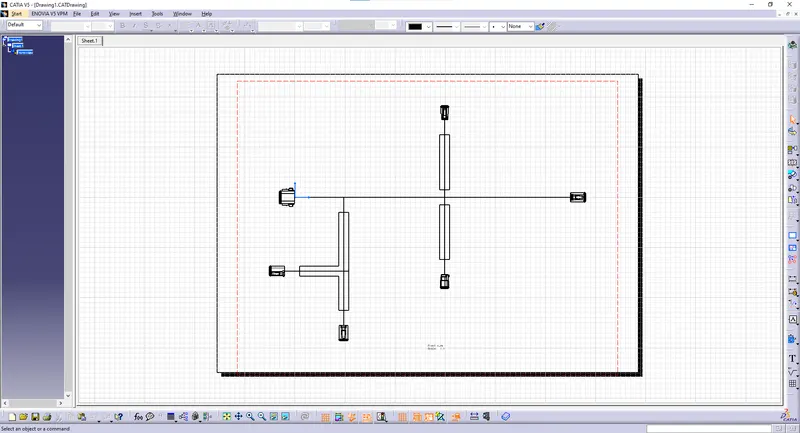
1.Open A new drawing in Catia & Select the face Then go to the flattening workbench select the same face of the connector & It will appear in drawing sheet.
2.before doing that make sure that you have to selected in a single line for bundle segment & Double line for protective coverings.
3. after that right click on drawing go through the properties & Enable 3d wireframe always visible.
4. As Shown in given figure below.
Result :
Sucessfully Placed the Flattened view on drawing Sheets with Different visuals on Protective Coverings.
All Necessary files are attached in ZiP Format (Including all files).