Wiring harness design in CATIA V5 - 3D modeling Week 7 Challenge
OBJECTIVE:
To flatten the Harness Assembly which was completed in Week 4 Challenge. Below is our objective
- To flatten the Harness Assembly.
- To place the flattened view on drawing sheet.
- To ensure bundles with protective coverings has different visuals on drawing view
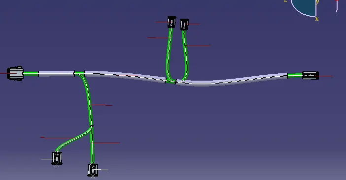
Fig:1 Harness Assembly of Week#4 Challenge
PROCEDURE:
STEP#1: To flatten the Harness Assembly.
In order to flatten the Assembly, We have to define the Flattening Parameters in “Electrical Harness Flattening Workbench”
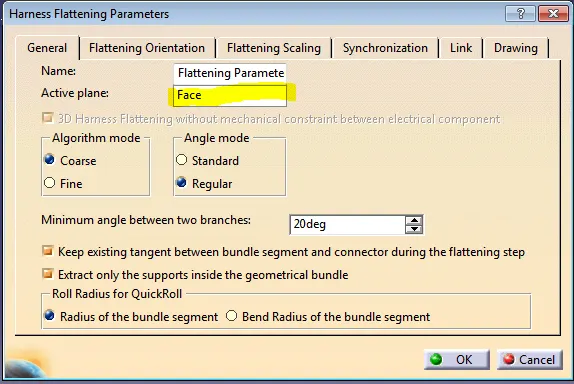
Fig:2 Flattening parameters(General tab)
As above image showing, we have to define the desired plane that we want to work on.
Select the desired parameters according to your requirements.
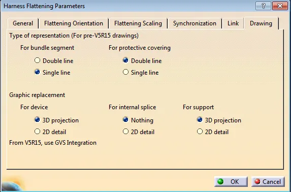
Fig:3 Flattening parameters(Drawing tab)
As above image showing, we have to ensure that the bundle segment and protective covering representation should be different from
each other just for recognizing purpose. Also for devices, we have to enable '3D Projection',if actual connectors were used in given electrical drawing.
Once we define the flattening parameters, it will reflect in model tree like below image:

Fig:4 Model Tree of Flattening File
Now, we have to bring Harness Assembly into newly created Flattening Product by using 'Extract" command in 'Electrical
Harness Flattening' workbench. Here, we have to tile both the files(Flattening Product file & Harness Assembly source file) vertically like below image.
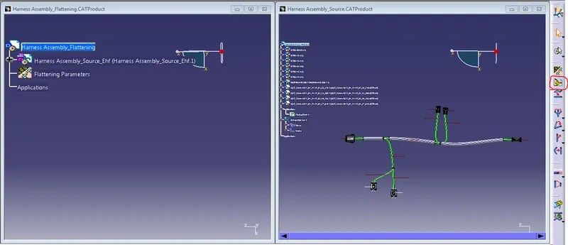
Fig:5 Flattening file and harness source file(Tiled Vertically)
Now, We have to flatten the given Harness Assembly and for that we have to choose plane or face of the connector after that
select all branches of the Harness Assembly(Like below image)
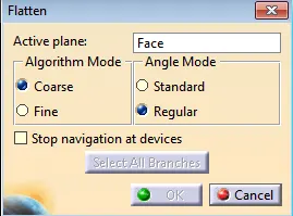
Fig:6 Flatten Command Window
Now, we have to use rotate,scale,Roll,Bend etc to make it look representable.
After that our resultant flatten file will look like below image.
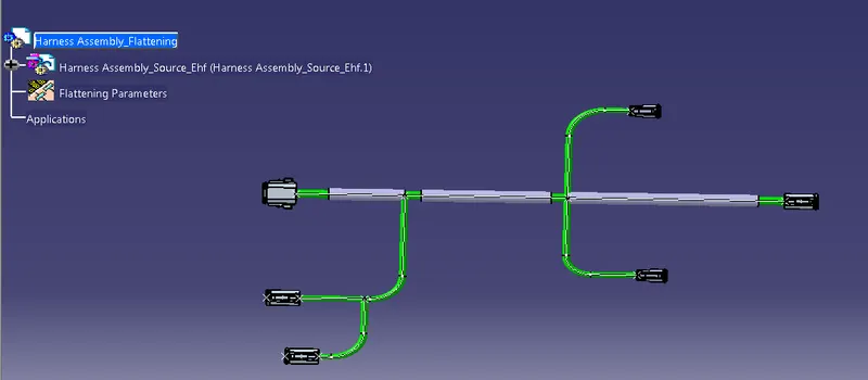
Fig:7 Resultant Flattening file.
Check for Bundle Continuity,update and save the file.
STEP#2: To place the flattened view on drawing sheet
Here, we have to create new drawing(File->New->Drawing) and provide the desired sheet parameters.
Here, we have to tile both the files(Flattening Product file & Drawing file) vertically like below image.
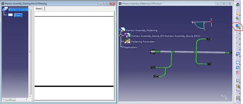
Fig:8 Flattening file and Drawing file(Tiled Vertically)
Then import the flatten file into drawing file by using 'Front View' command which was highlighted in red in above image.
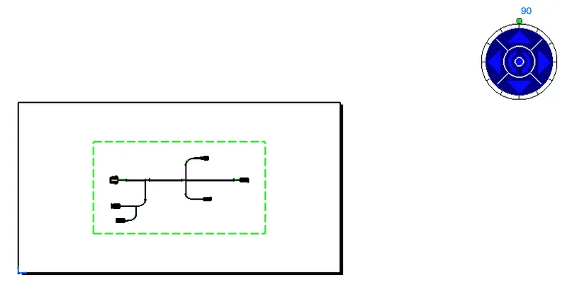
Fig:9 Drawing file (after using front view command)
As shown in above image, the flattened file has been imported and oriented in our desired manner.
Now, click anywhere on screen of drawing file. At this point we'll have reached below stage.
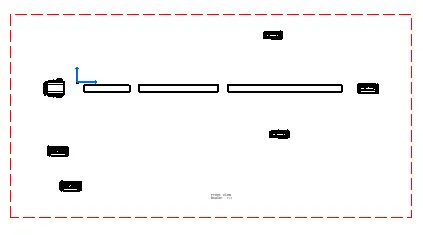
Fig:10 Drawing file (after clicking on screen)
Now, we have to provide properties to drawing file. Inorder to make the connection visible between the connectors like below image.
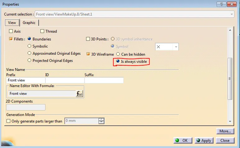
Fig:11 Properties of Drawing file
Now, we have sucessfully placed the flattened view on drawing sheet.
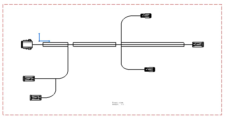
Fig:12 Completed Drawing file
STEP#3: To ensure bundles with protective coverings has different visuals on drawing view
As you can see below, the bundle segment is represented in 'Single line' and the protection covering is represented in 'Double line'
If you want to change the representation then we have to modify the flattening parameters accordingly.
Fig:13 Completed Drawing file
Here, we have used the colors for 3D projected devices as shown in below image.
But the recommended look is to keep drawing view black and white for better understanding.
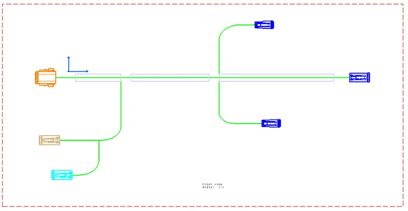
Fig:14 Color view of Drawing file
RESULT:
Thus all our objectives have been completed and the files were attached for manual review.