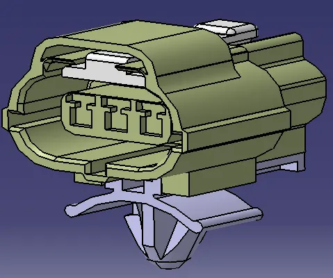
Wiring harness design in CATIA V5 - 3D modeling Week 2 Challlenge
FOLLOWED THE BELOW STEPS TO DEFINE COMPONENTS AS ELECTRICAL IN CATIA V5:
- Downloaded & loaded the 3D file(stp or igs) into CATIA V5.
- Opened Mechanical Design--> Part Design. Then Defined all the required Geometrical Parameters(Conenctor-Connection Point,Bundle Entry point & Connector-Connection Axis).
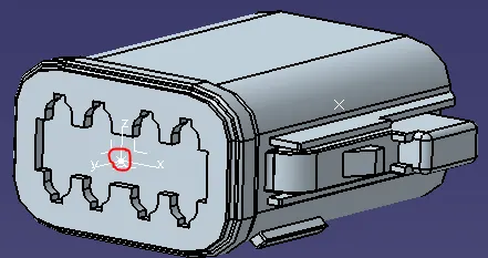
a) Connector-Connection Point:It's the point that goes on Mating Face of the connector(Like Below Image)
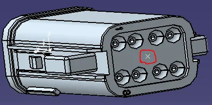
b) Bundle Entry Point: It's the point that goes on Wire entry side of the connector(Like Below Image)
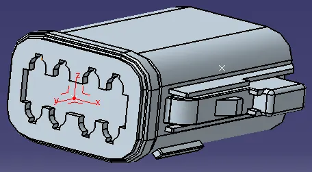
c) Connector-Connection Axis: It's the axis that contains the Mating-Connector Orientation, Locking Mechianism Direction(Like Below Image)
y-axis--> should be pointing towards the mating face of the connector.
x-axis--> should be pointing towards the locking mechanism of the connector.
z-axis--> should be pointing across the connector from left to right or top to bottom.
3. After defining all the Geometrical Parameters . Switched to "Electrical Part Design" Workbench.
4. Defined the below Properties to make it an Electrical Component.
a) Define Connector
b) Define Bundle Entry Point.
c) Define Connector-Connection Point
d) Define Cavity Connection Point( If the feauture was available in the Connector)
5. After defining all these parameters. The below symbol was appeared confirming that the component has been successfully defined as Electrical Part.

6. Save the Part & Add to the Catalog as a library.
RESULTANT CONNECTORS & ASSEMBLY:
Deutsch DT06 – 08SA
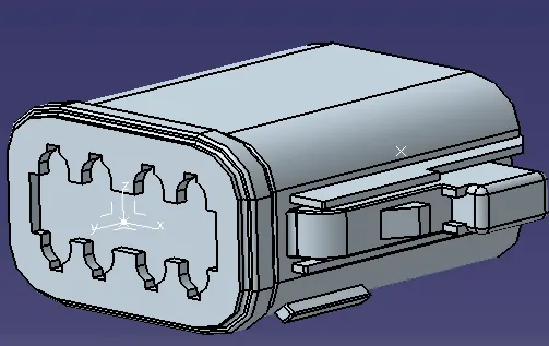
Tyco 174357-2:
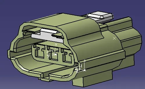
Tyco 85229-1:
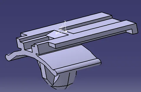
Assembly_Tyco 174357-2 & 85229-1: