Wiring harness design in CATIA V5 - 3D modeling Week 5 & 6 Challenge
OBJECTIVE:
To create a harness layout in Electrical workbench and perform below tasks while doing so:
- Check the bundle Continuity. Add snap of result in submission
- Add annotation to all connectors. Make an assumptions for annotations like connect 1 , 2 etc
- Check for the bundle warning. Add snap.
- Generate CAT.part of harness assembly and convert is in. igs format.
STEPS:
1.Bundle continuity of Harness assembly-A & B:
This will check the bundle connection and it's true value of all branches meaning whether all the bundles are fully connected with each other or not(ref below image).
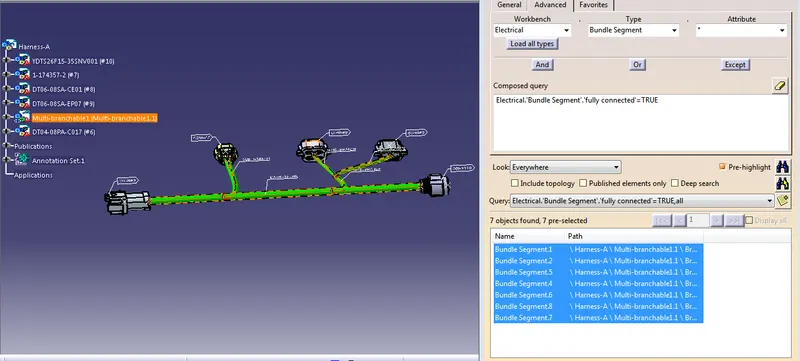
Fig 1.1: Bundle Continuity of Harness-A(TRUE Attribute Analysis)
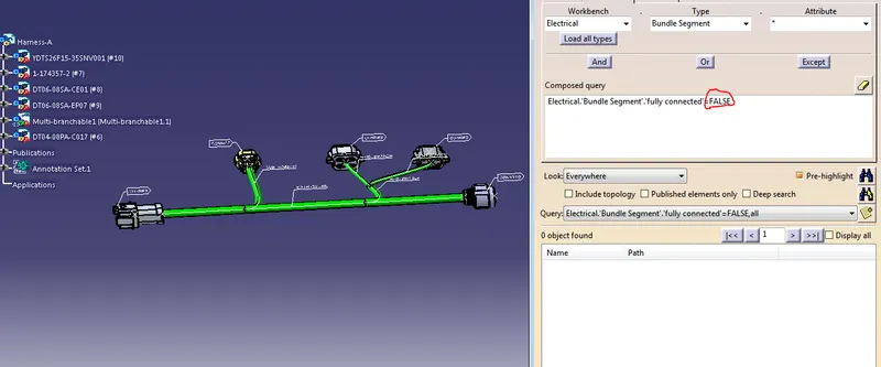
Fig 1.2: Bundle Continuity of Harness-A(FALSE Attribute Analysis)
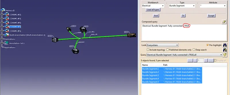
Fig 2.1: Bundle Continuity of Harness-B(TRUE Attribute Analysis)
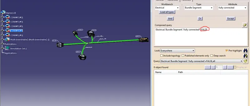
Fig 2.2: Bundle Continuity of Harness-B(FALSE Attribute Analysis)
As you can see above, all the bundle segments in both harnesses A & B are fully connected.
2.Annotation to all connectors in Harnesses A & B:
It's added to show the function of the connector/unit and information related to harness like it's spec,designation,Wire Type or any other details that needs to be specified.
In this case the connectors were named as "CONN#1,CONN#2...," and so on.
the Wiring segments were named as "Main Trunk & Sub-Branch"(ref below image)
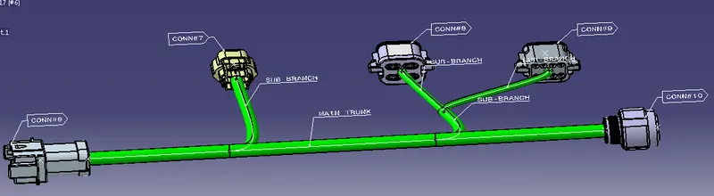
Fig 3: Annotations of Harness-A
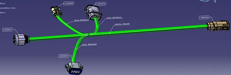
Fig 4: Annotations of Harness-B
3.Check for the bundle warning:
Bundle Warnings are usually dispalyed in the tree structure of the Wriring Harness Geometrical Bundle.
It's mostly related to Bending Radius,Bundle Diameter or the Vector Position of bundle segments.
It's denoted by "YELLOW EXCLAMATION(!)" mark on Multi-Branchable Product.
In this Case, Refer below Image.
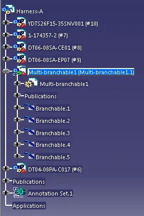
Fig 5: Harness-A(Munlti-Branchable Product)
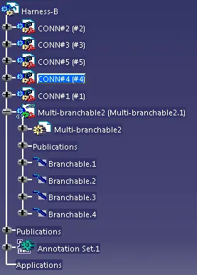
Fig 6: Harness-B(Munlti-Branchable Product)
As you can see above, there are no yellow exclamation mark on Multi-Branchable Product meaning there is no Bundle warning.
It's good to go.
4.Generate CAT.part of harness assembly A and B and convert is in. igs format.
Sometimes it's necessary to create CATPart of 3D Wire Harness for Review or Releasing Purposes.
Access "Generate CATPart from Product" from Mechanical Assembly Design Workbench.
and save it as "STEP or IGES" file for the conversion.
Interconnecting Harnesses A & B:
Place the Harnesses A & B in a Product file and connect the CONN#5 & CONN#6 by "Connect Electrical Devices" Command.(ref below image)
And Convert it to IGES or STEP file for review and release purposes.
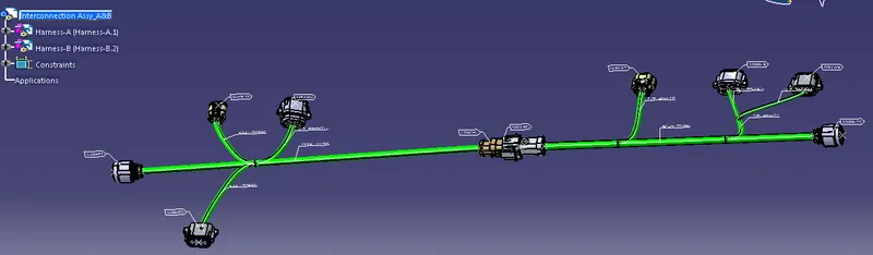
Fig 7: Interconnection of Harness-A&B
RESULT:
Thus the wiring Harness layout has been created and the desired tasks have been performed.
The same file have been attached for Manual review.