Wiring harness design in CATIA V5 - 3D modeling Week 5 & 6 Challenge
In this work I have done Harness Layout in Electrical WorkBench.
At First the given Parts are defined as an Electrical Part by Define Connector, Connector Connection Point and Bundle Connection Point.
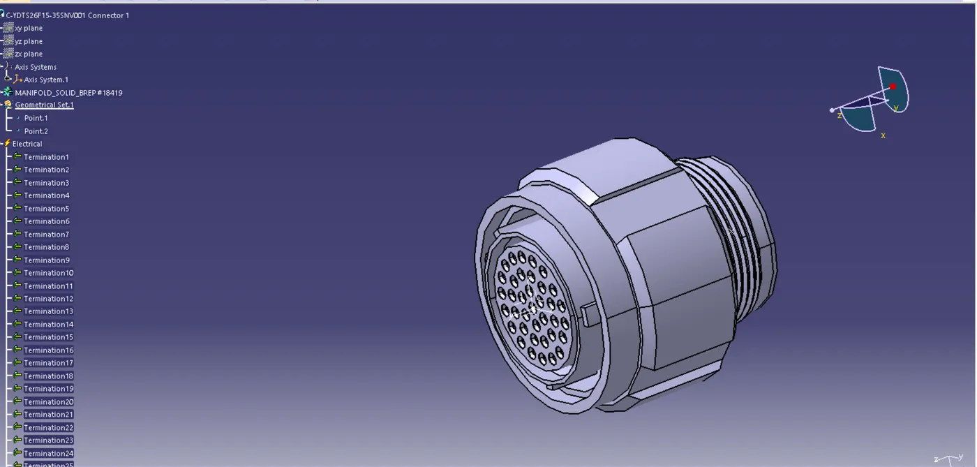
Fig 1. Harness B Connector 1
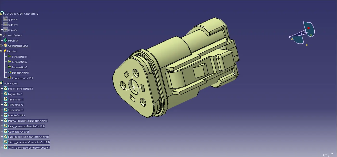
Fig 2. Harness B Connector 2
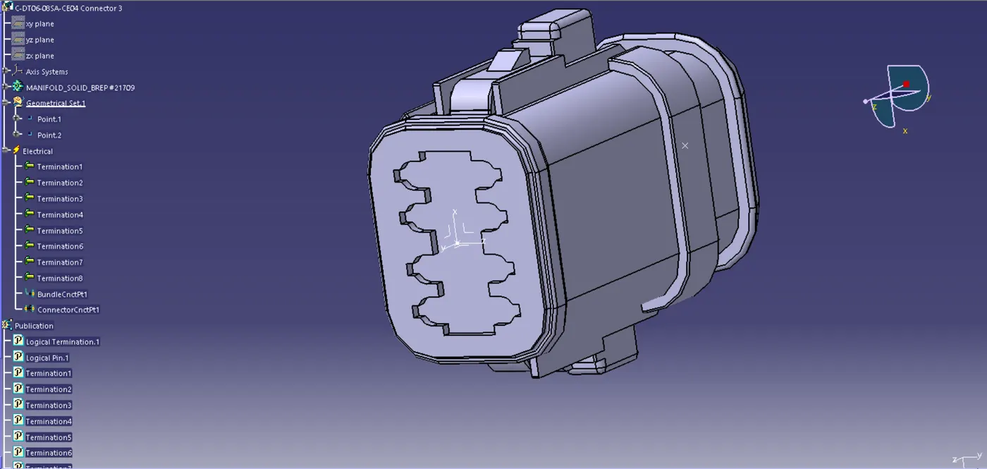
Fig 3. Harness B Connector 3
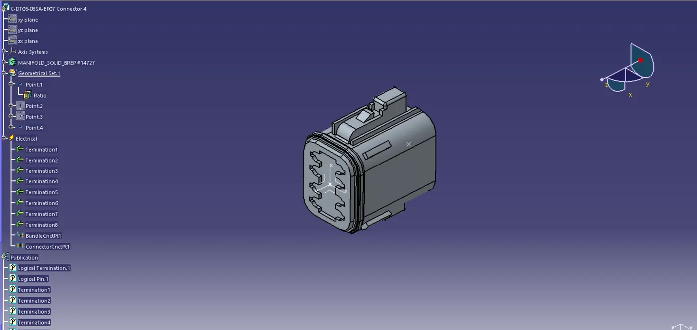
Fig 4. Harness B Connector 4
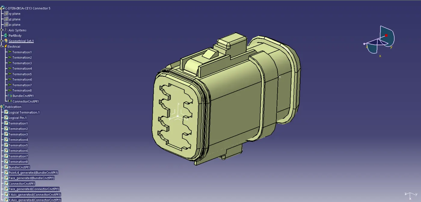
Fig 5. Harness B Connector 5
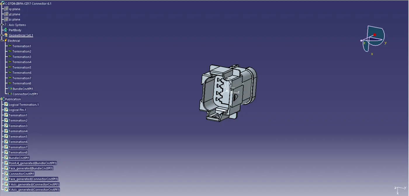
Fig 6. Harness A Connector 6
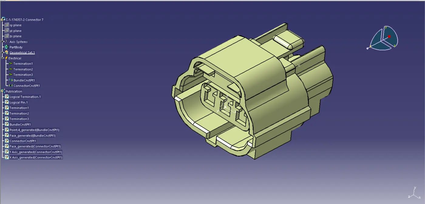
Fig 7. Harness A Connector 7
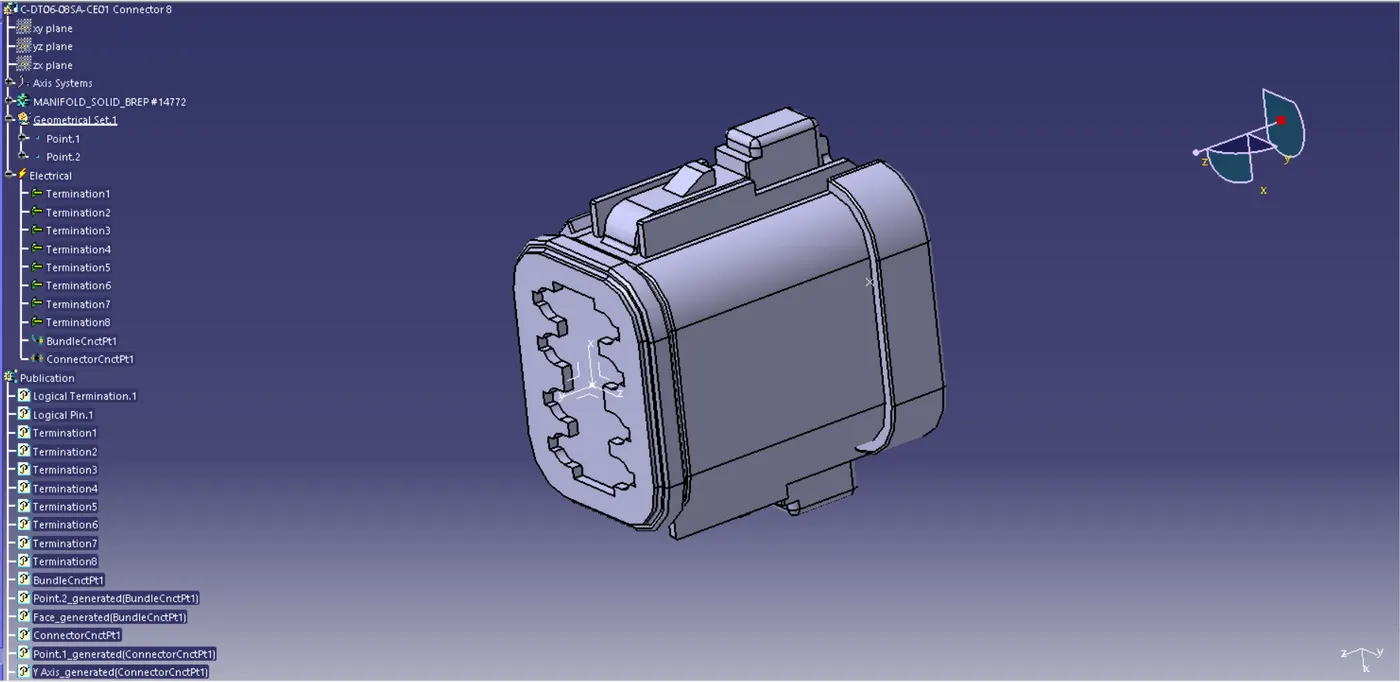
Fig 8. Harness A Connector 8
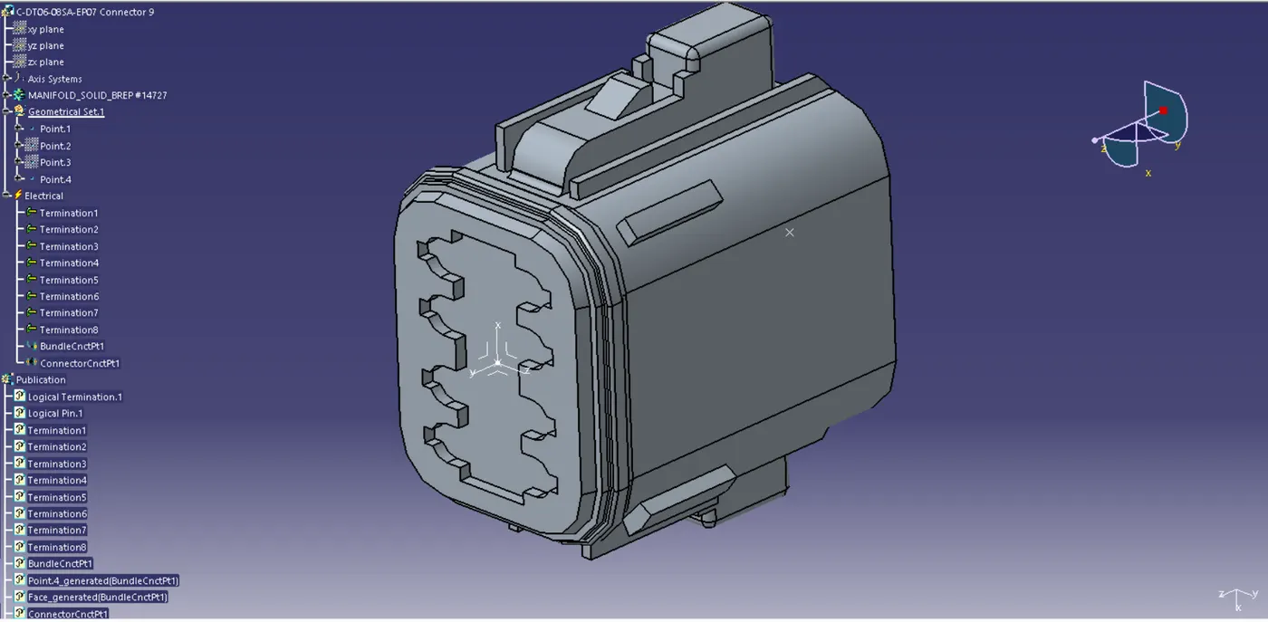
Fig 9. Harness A Connector 9
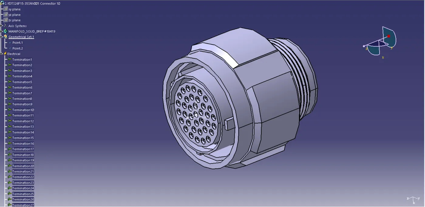
Fig 10. Harness A Connector 10
Then the Parts are Assembled in the Electrical Harness Assembly according to the Mapping Data. The Parts are separated into Harness A and Harness B. Both are opened in a separate window and the Title is defined with the Geometrical Bundle. Then the Branch is created with Multi-Branchable Document Option and the Connectivity is checked for the Branch. Then Protective Covering is created over the Branch.
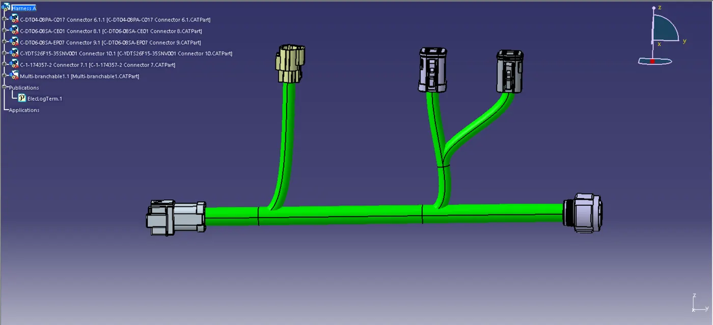
Fig 11. Harness A Assy with Multi-Branchable
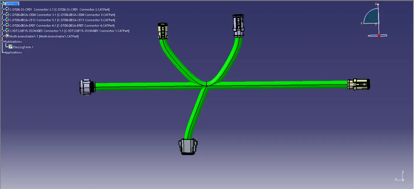
Fig 12. Harness B Assy with Multi-Branchable
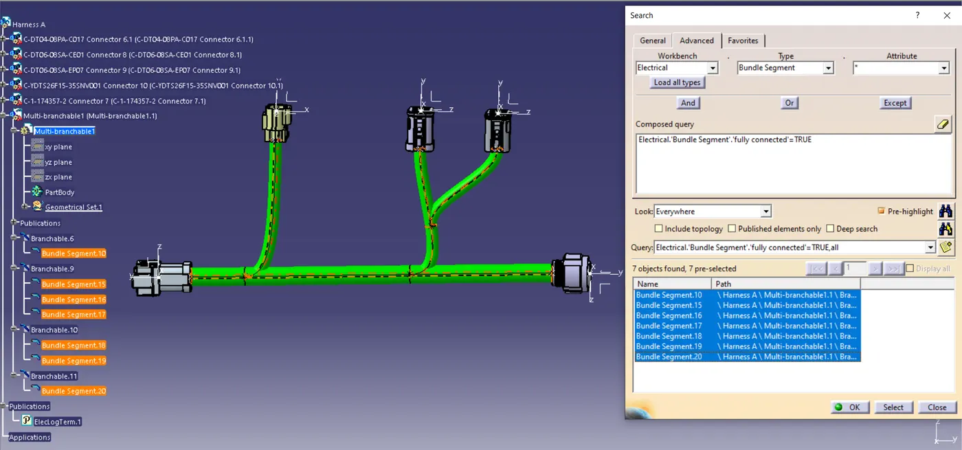
Fig 13. Harness A Connectivity Check
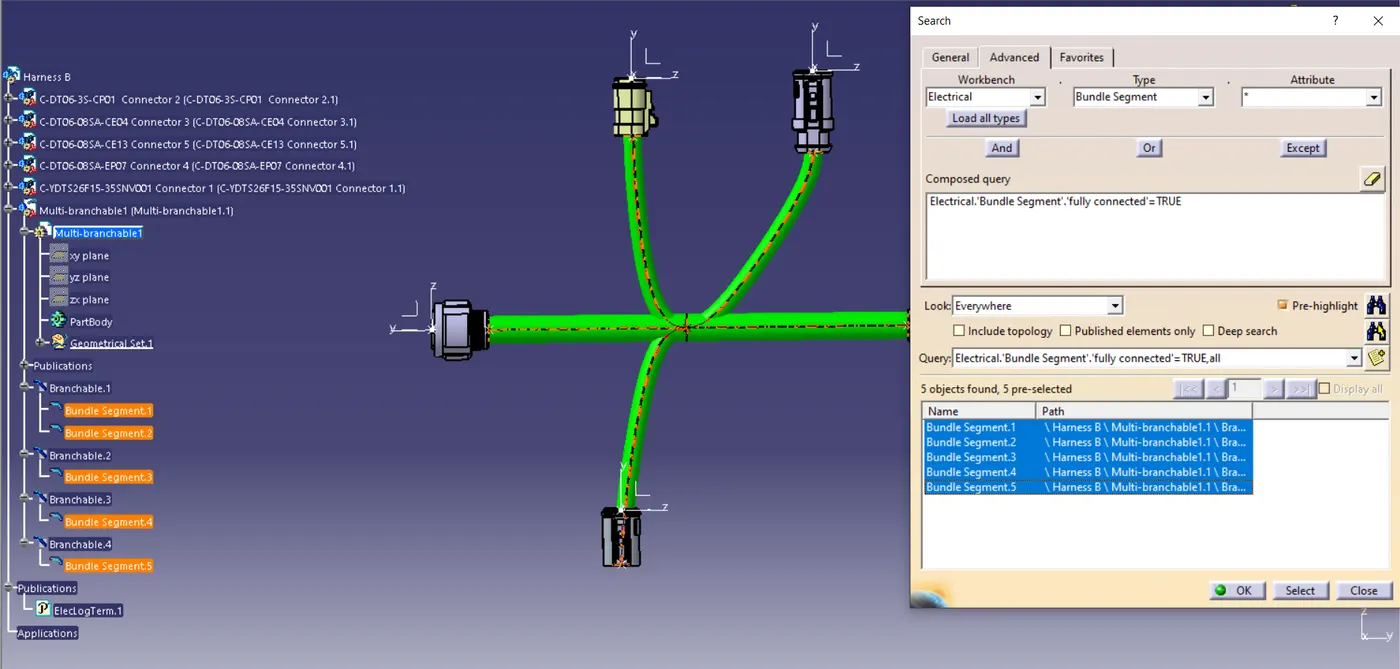
Fig 14. Harness B Connectivity Check
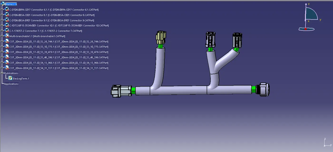
Fig 15. Harness A with Protective Covering
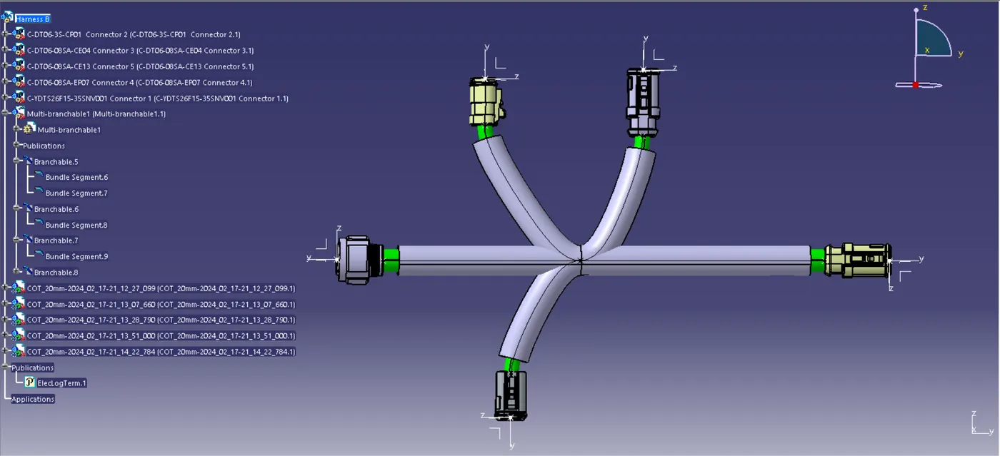
Fig 16. Harness B with Protective Covering
Now the Harness A and Harness B is taken in a Product file and changed to Electrical Assembly Design. Then the Connector 5, 6 are Connected and the Annotations is done for the Parts.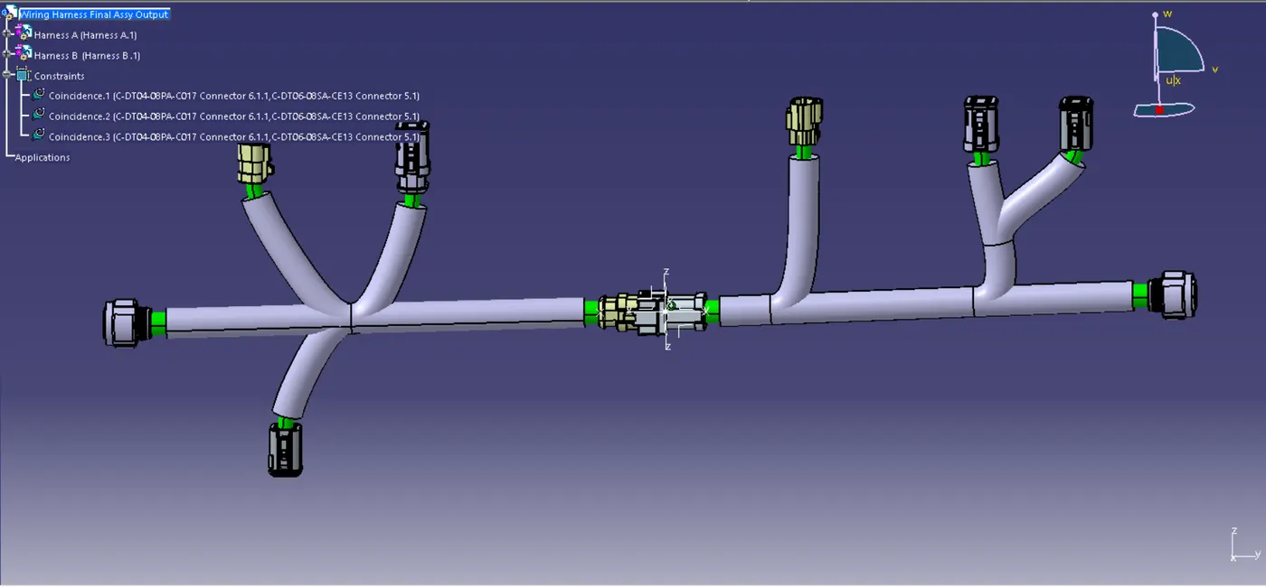
Fig 17. Wiring Harness Final Assy Output
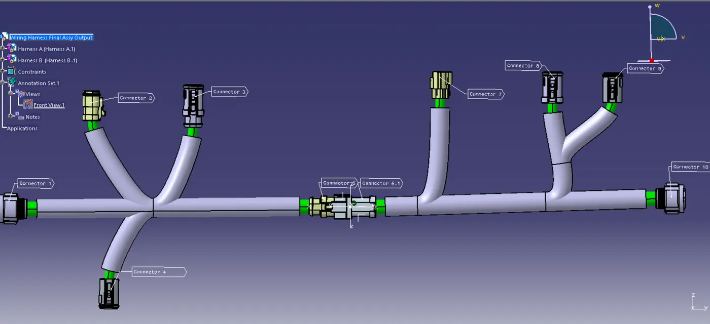
Fig 18. Annotations
Then from the Electrical Assembly WorkBench the Assy is changed to the Mechanical Assembly Design. In this workbench select the Tools Option. In Tools select the Generate CADPart from Product option and change to IGS File formet.
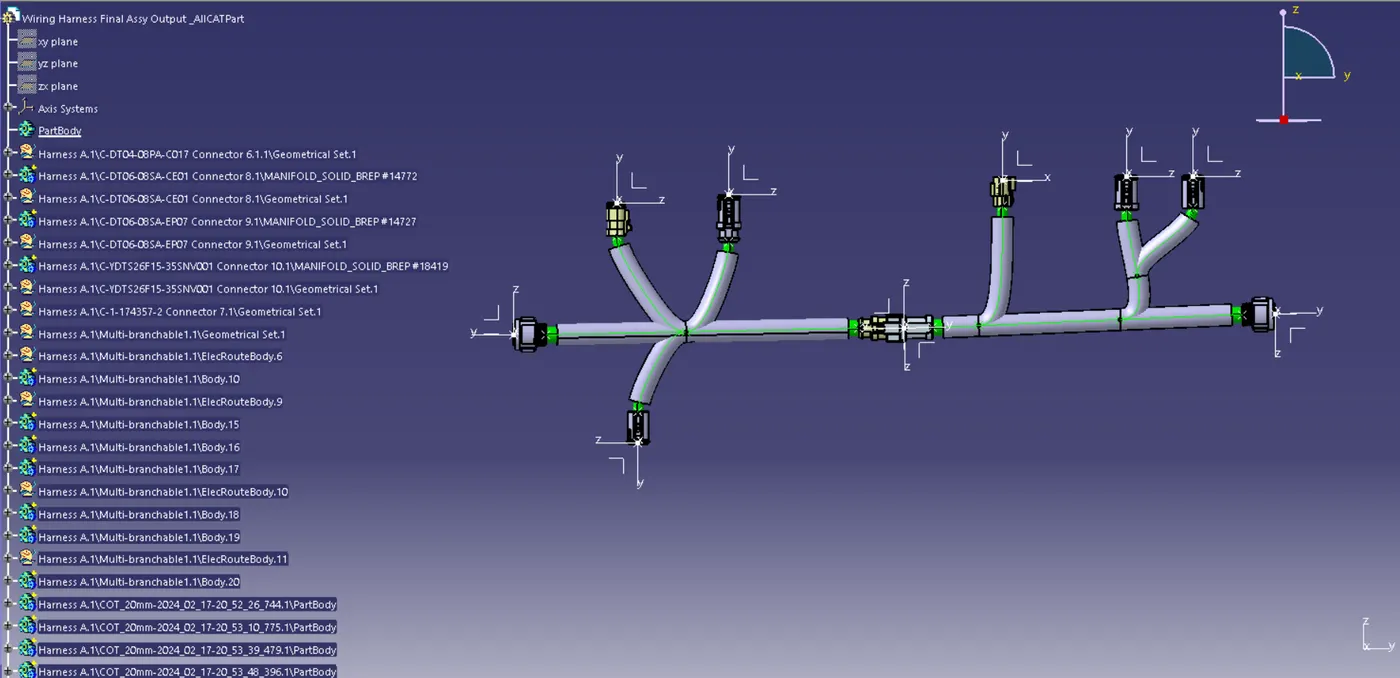
Fig 19. Converted CADPart File into IGS File