Wiring harness design in CATIA V5 - 3D modeling Week 5 & 6 Challenge
Wiring harness design in CATIA V5 - 3D modeling Week 5 & 6 Challenge
OBJECTIVE: To proficiently route the given harness layout within the Electrical workbench of CATIA by assumptions harness bundle diameters and utilizing the provided connectors. Upon successful routing, the following tasks should be accomplished:
1) Bundle Continuity Check
2) Connector Annotation
3) Bundle Warning Check
4) CATIA Part Generation
5) Conversion to .igs Format
GIVEN DATA:
Wiring Harness Layout:
MAIN PROJECT:
STEP-1: Download all the CAD data provided for all the connectors and define the required geometric properties.
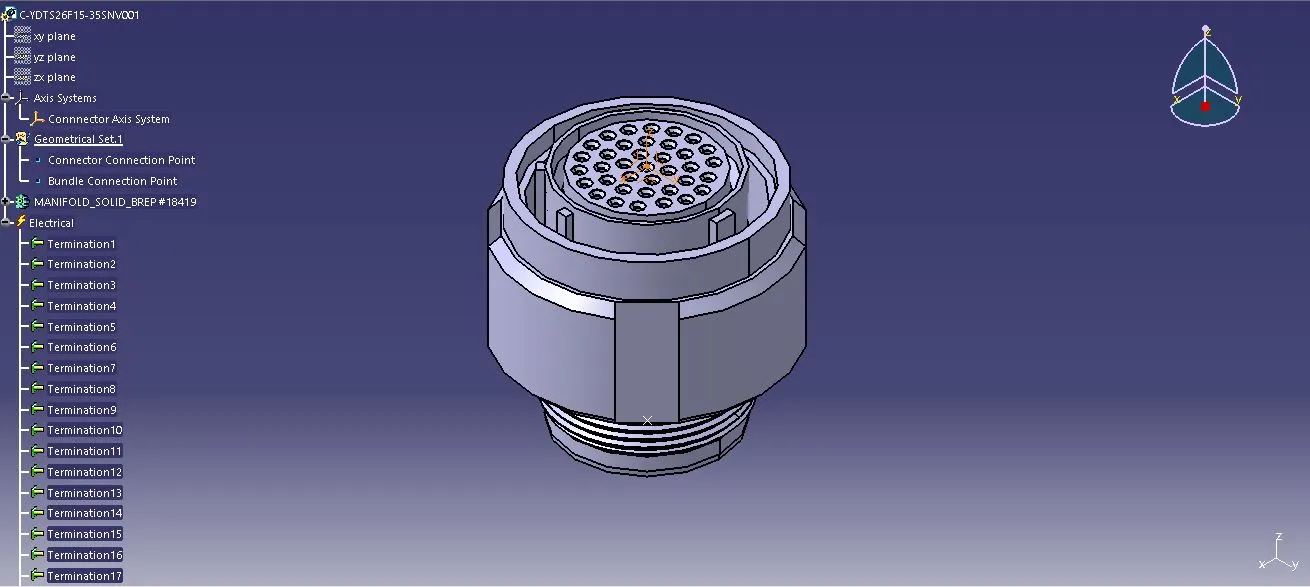
1) C-YDTS26F15-35SNV001:
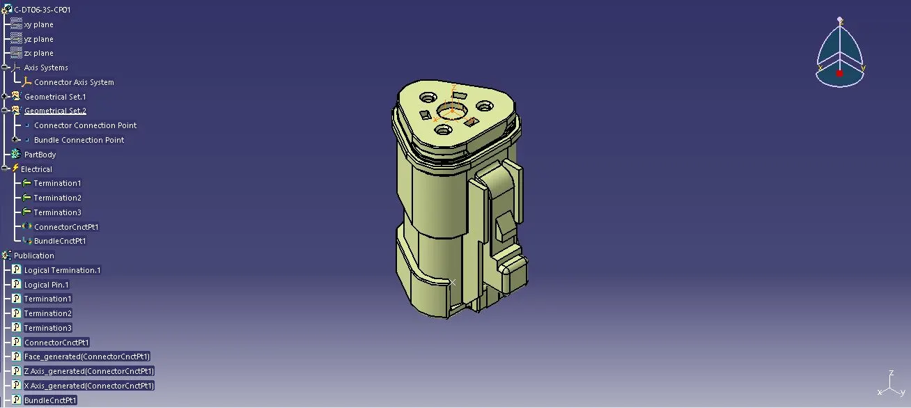
2) C-DT06-3S-CP01:
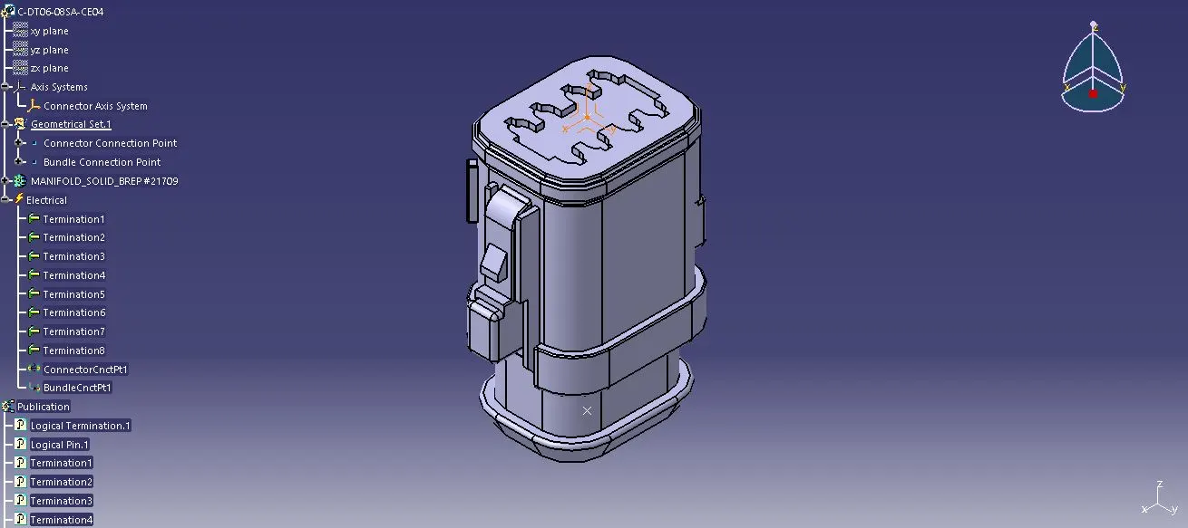
3) C-DT06-08SA-CE04:
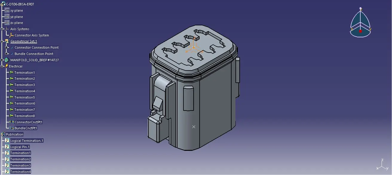
4) C-DT06-08SA-EP07:
5) C-DT06-08SA-CE13:
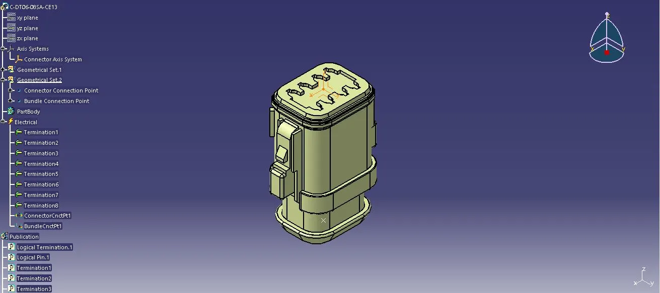
6) C-DT04-08PA-C017:
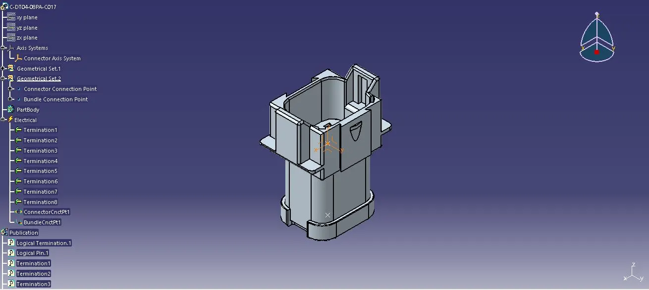
7) C-1-174357-2:
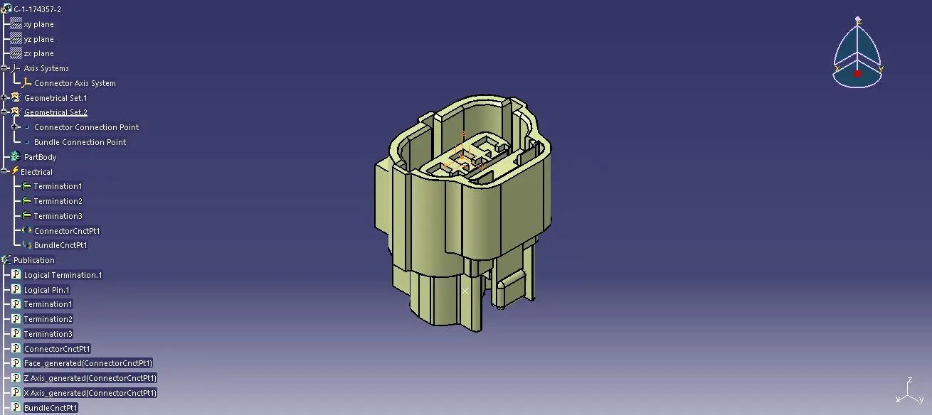
8) C-DT06-08SA-CE01:

9) C-DT06-08SA-EP07:
10) C-YDTS26F15-35SNV001:
HARNESS B Wire Routing:
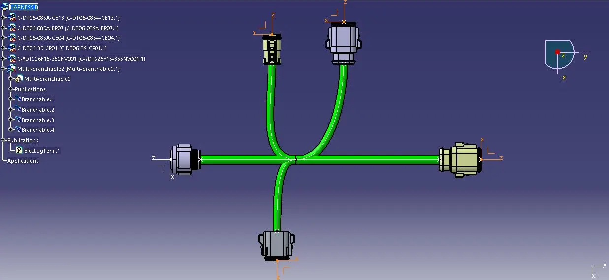
STEP-2: Create a new product "Harness B" and import the first 5 connectors in the product file. Position and align the connectors as per the given wiring harness layout.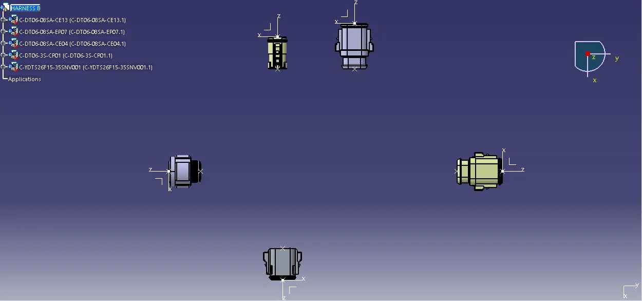
Switch from Mechanical Assembly Design Workbench to Electrical Assembly Design Workbench
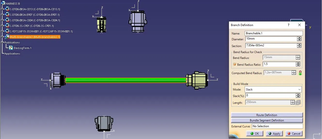
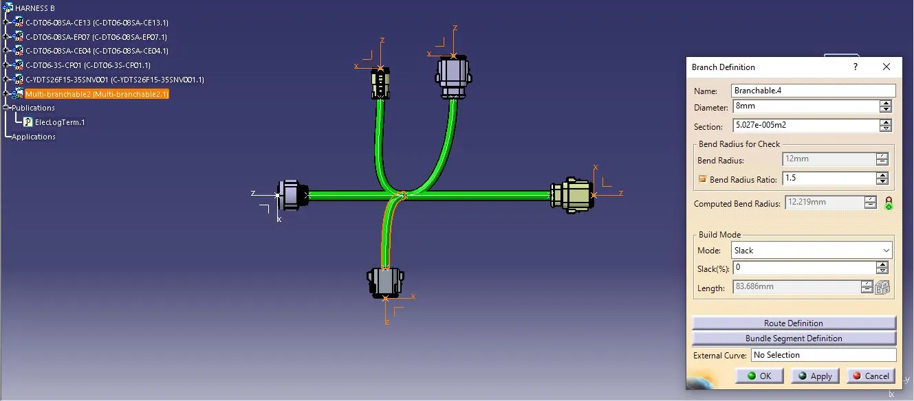
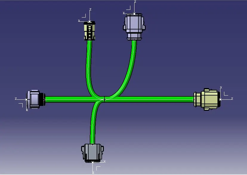
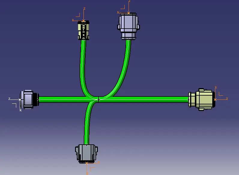
STEP-3: Define the product as a Geometrical Bundle and then use the Branch Definition option under Multi-Branchable Document to route the connectors 1 and 5 with the required bundle diameter, length and routing direction.
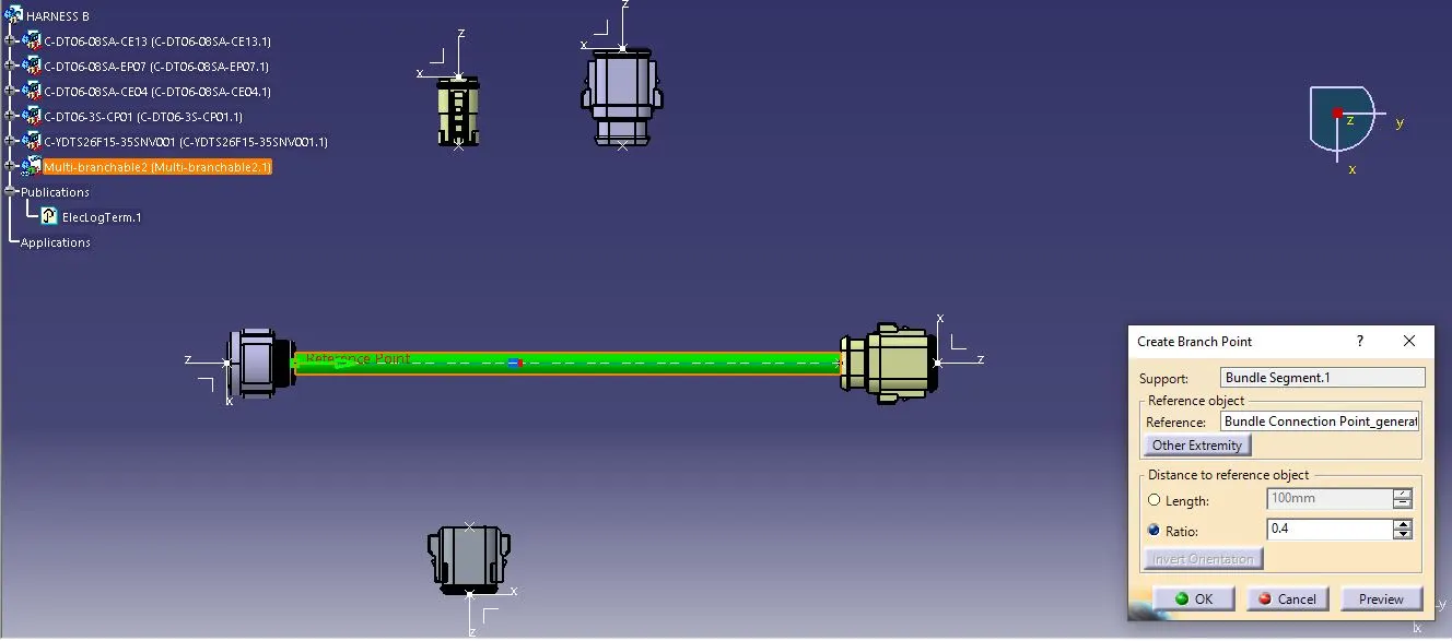
STEP-4: Add a branch point using the Add Branch Point option under Multi-Branchable Document at a 100 mm distance from the connector 1 end.
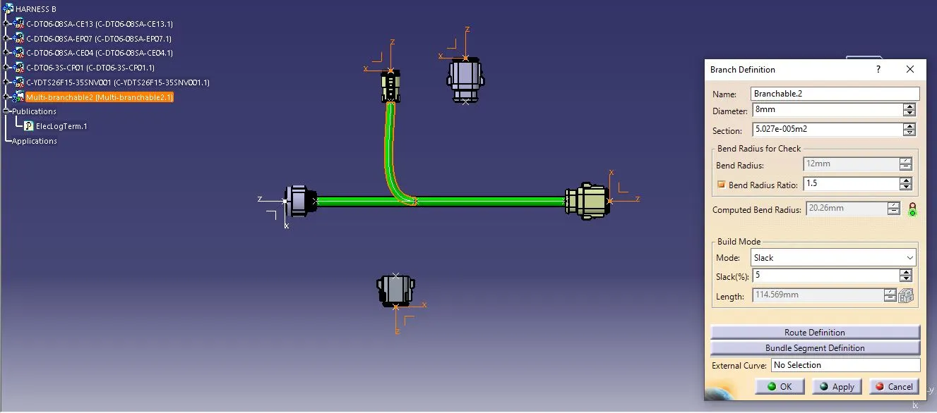
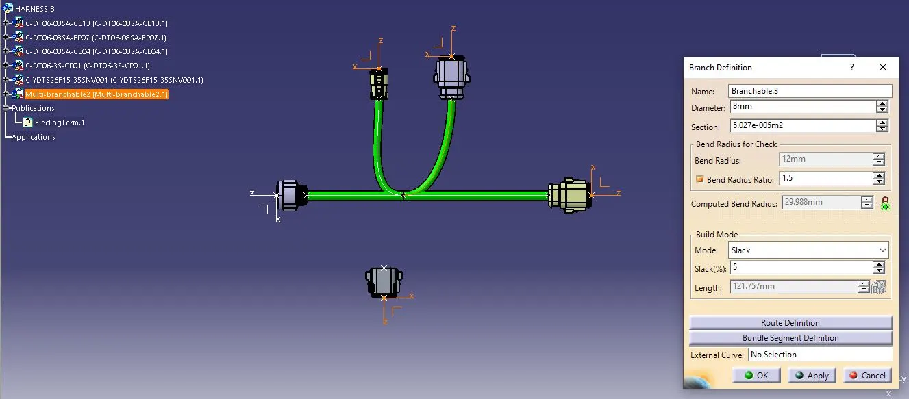
STEP-5: Again use the Branch Definition option to connect the main trunk from the branch point to connectors 2,3 and 4 with the 8mm bundle diameter with the appropriate slack percentage.
HARNESS A Wire Routing:
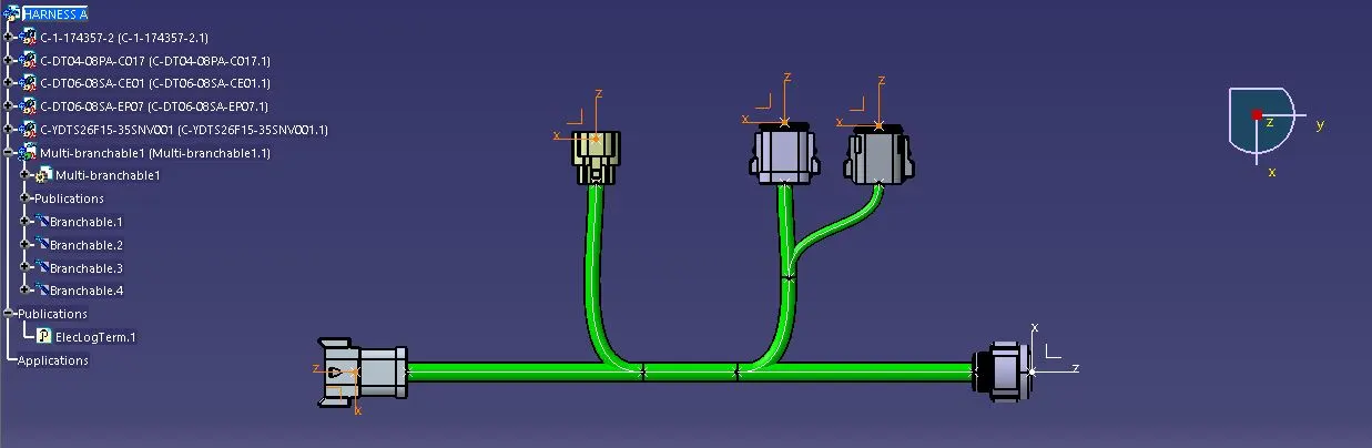
STEP-6: Create a new product "Harness A" and import the last 5 connectors in the product file. Position and align the connectors as per the given wiring harness layout.
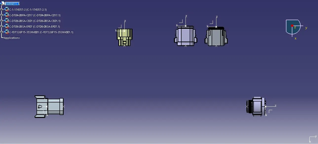
Switch from Mechanical Assembly Design Workbench to Electrical Harness Assembly Workbench
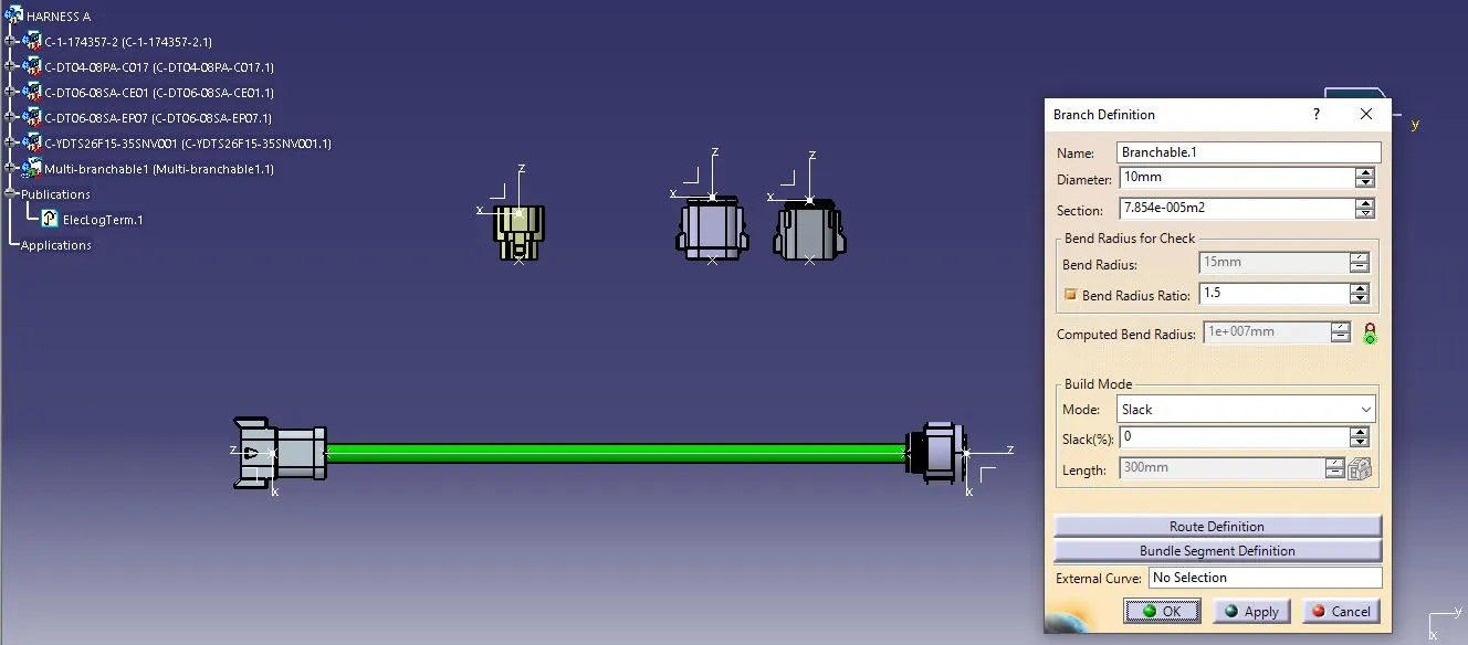
STEP-7: Define the product as a Geometrical Bundle and then use the Branch Definition option under Multi-Branchable Document to route the connectors 6 and 10 with the required bundle diameter, length and routing direction.
STEP-8: Add two branch points using the Add Branch Point option under Multi-Branchable Document at a 125 mm distance from both connector ends.
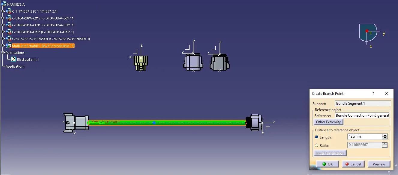
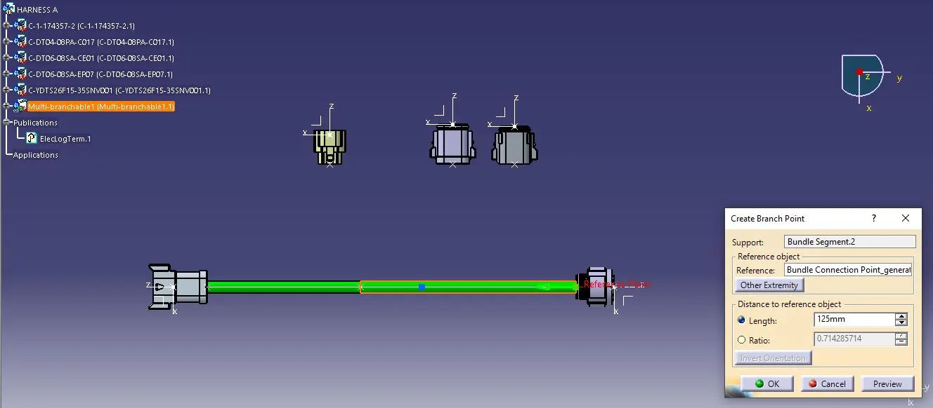
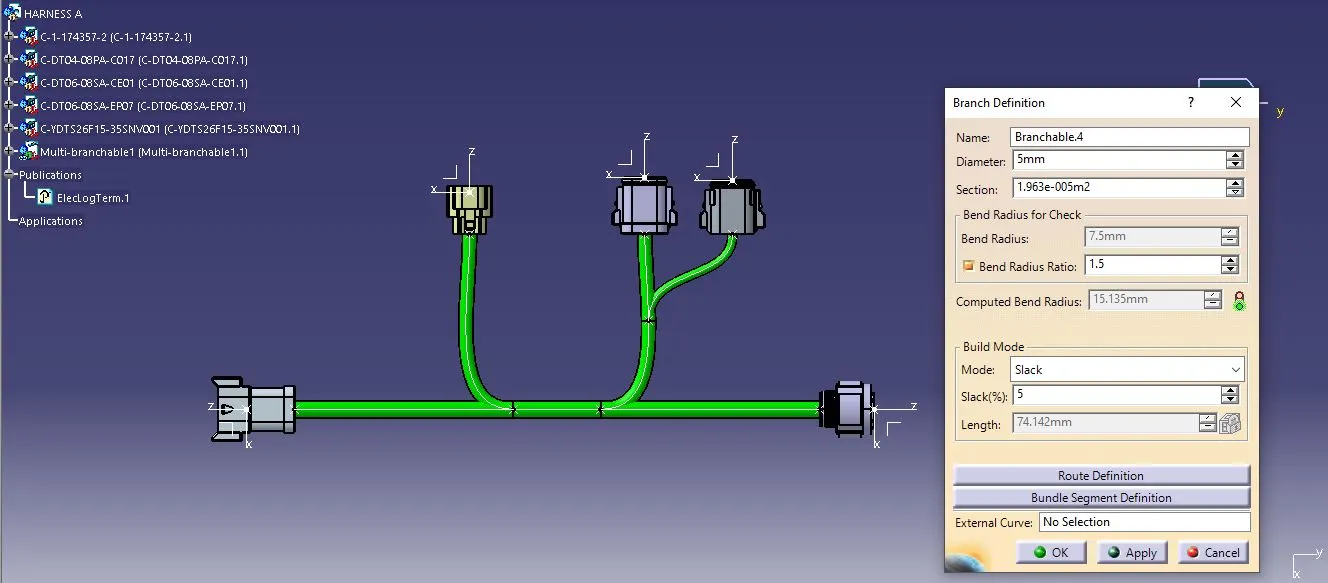
STEP-9: Again use the Branch Definition option to connect the main trunk from the branch points to connectors 7 and 8 with the 8mm bundle diameter with the appropriate slack percentage.
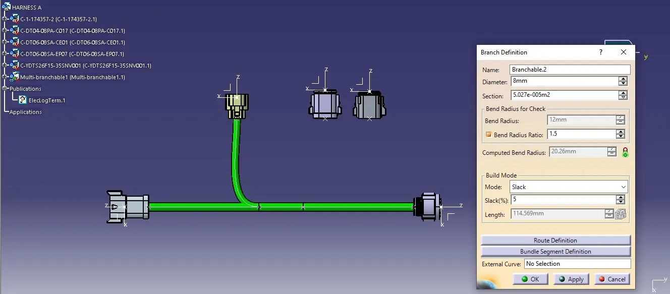
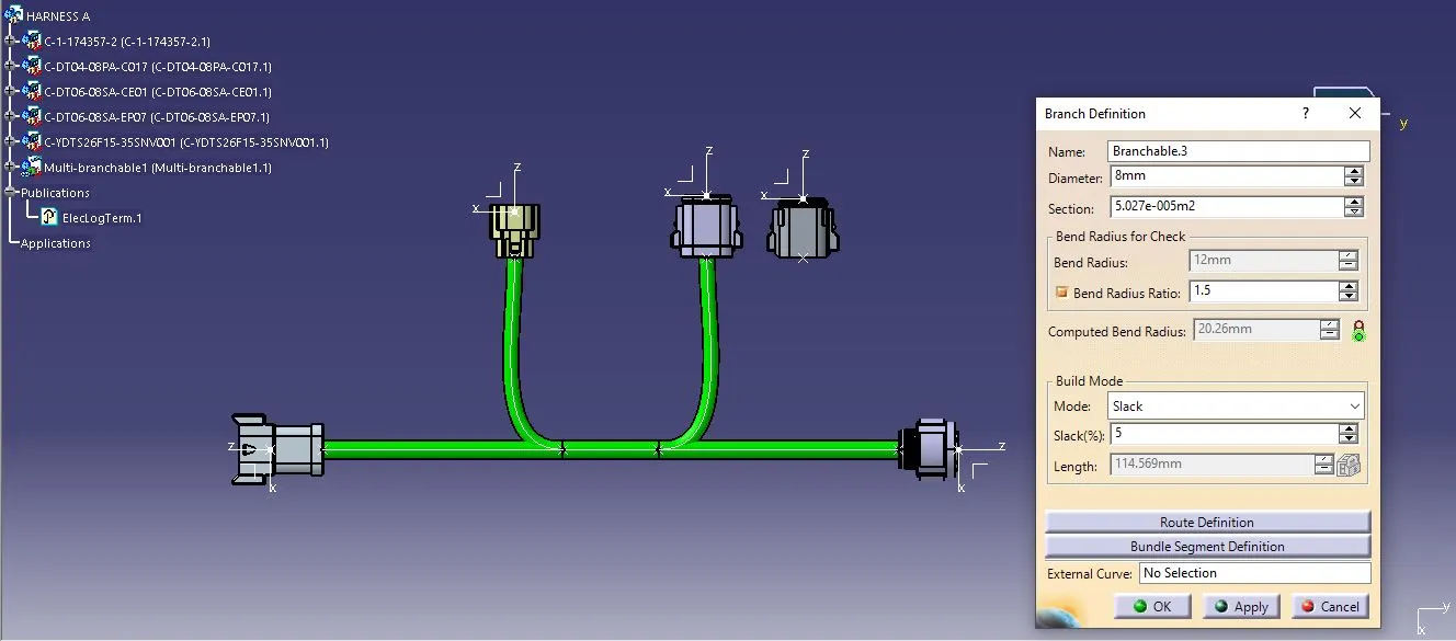
STEP-10: Again add a branch point using the Add Branch Point option under Multi-Branchable Document at a 65 mm distance on the bundle segment 5.
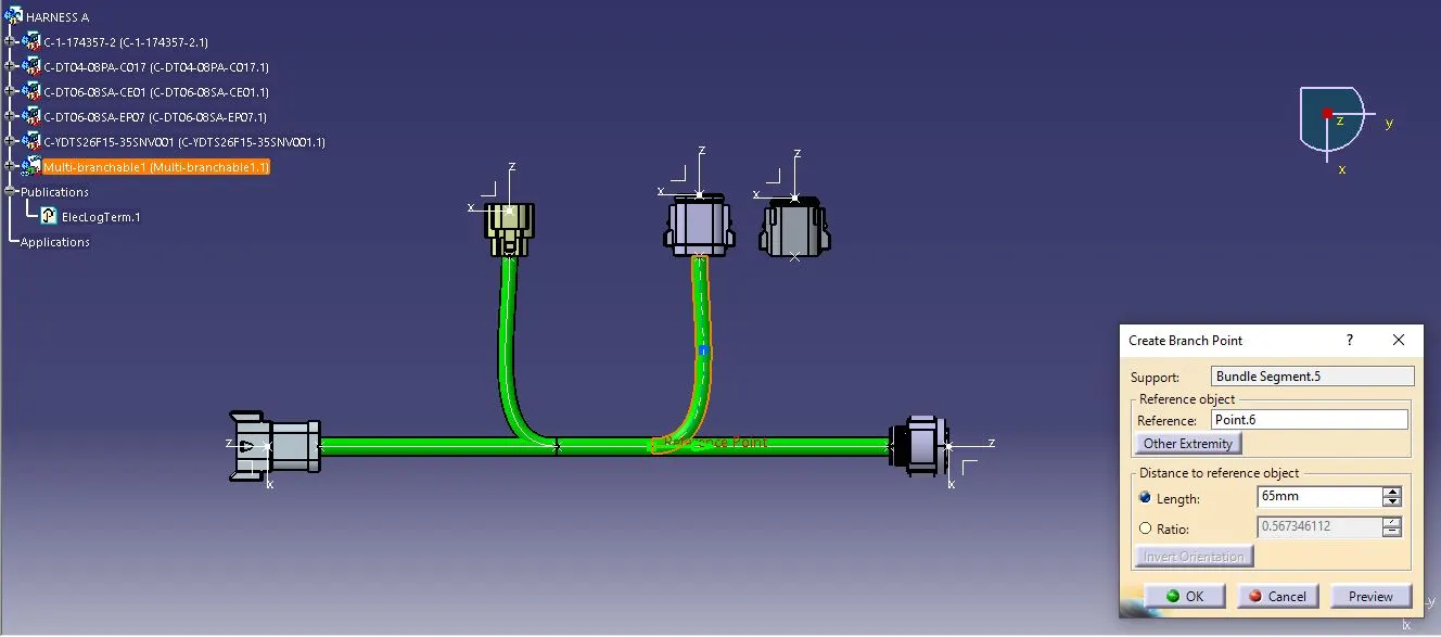
STEP-11: Again use the Branch Definition option to connect the branch segment 5 from the branch point to connectors 9 with 6mm bundle diameter with the appropriate slack percentage.
Wiring Harness Assembly:
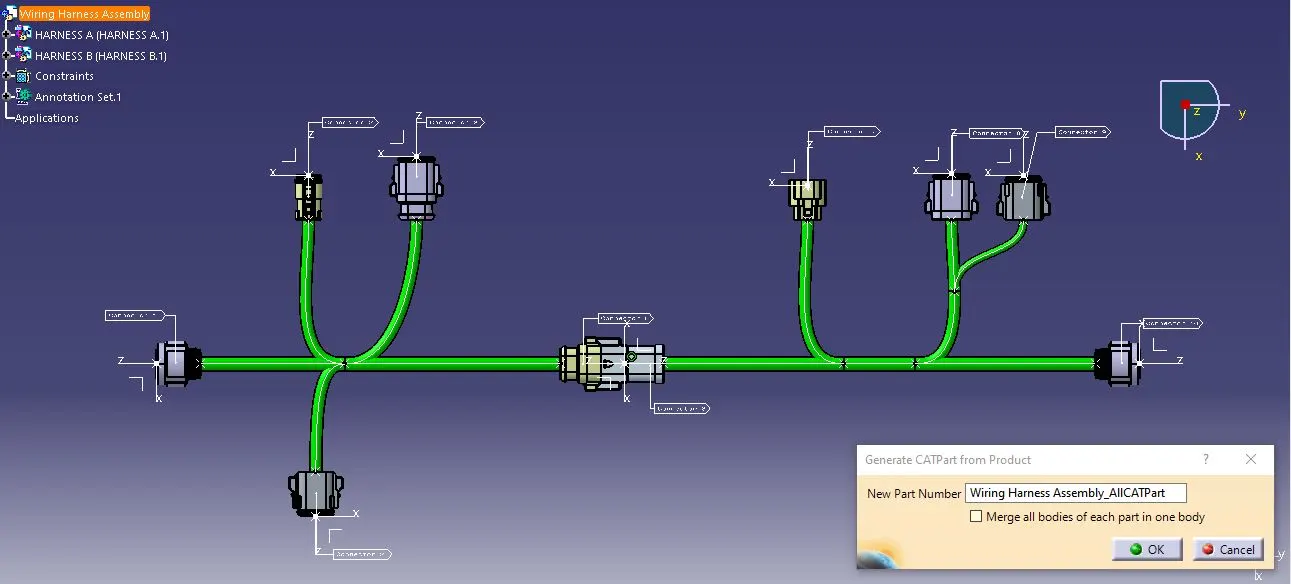
STEP-12: Create a new product "Wiring Harness Assembly" and import both the Harness A & B routing in the product file and position them as per the given wiring harness layout.
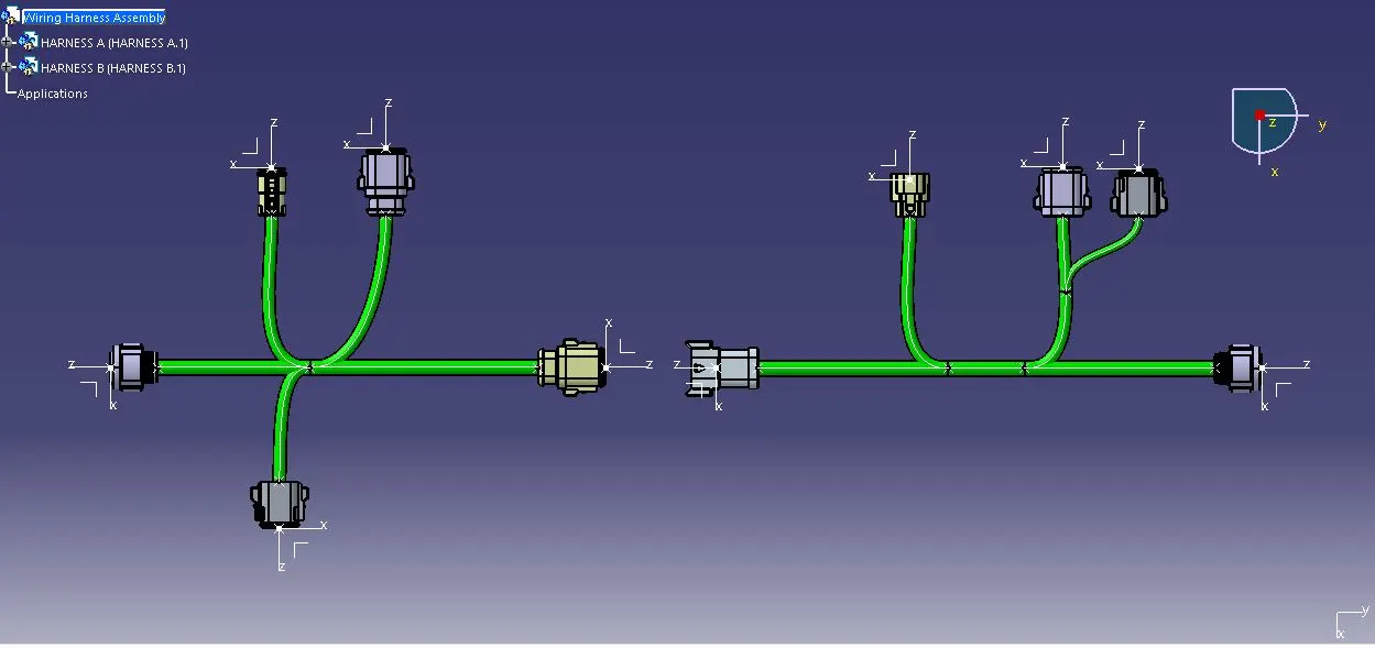
STEP-13: Using the Connect Electrical Devices option, join connectors 5 and 6 by selecting the connector connection point of both connectors.
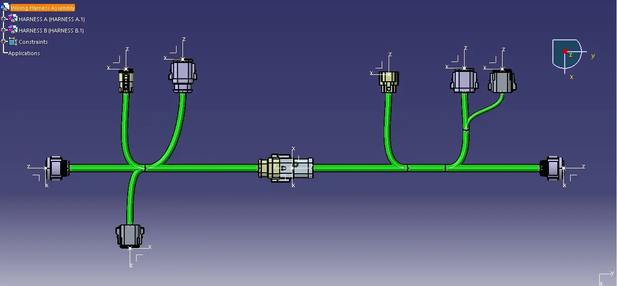
Switch from Electrical Assembly Design Workbench to Electrical Harness Assembly Workbench
STEP-14: Bundle Continuity Check
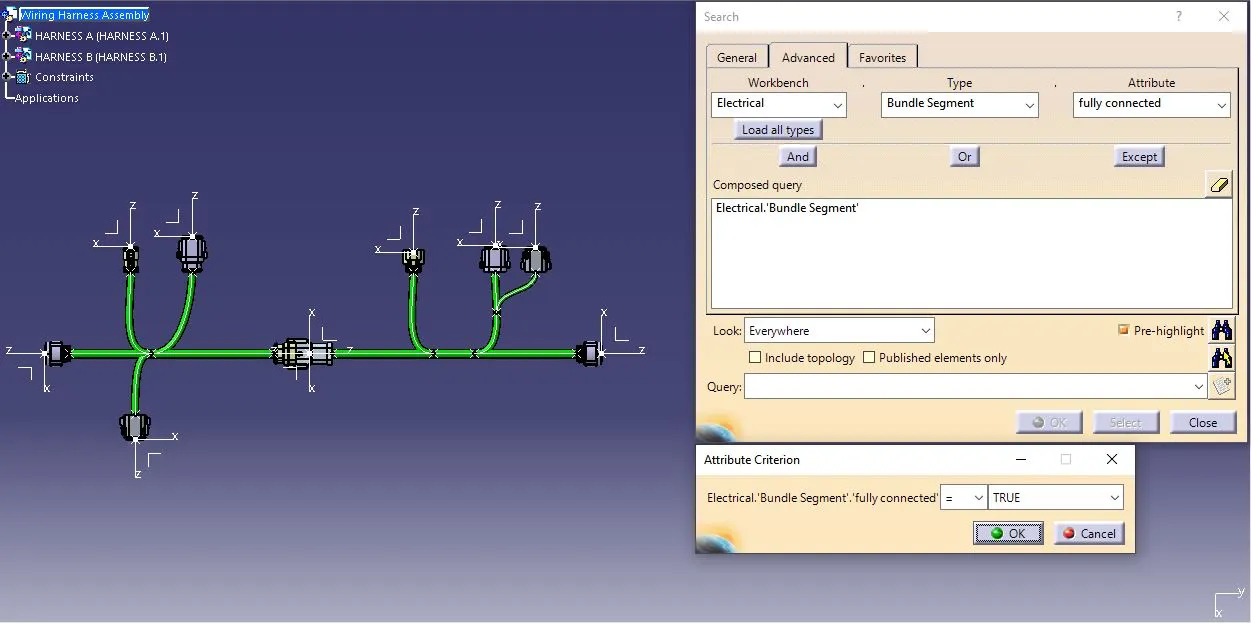
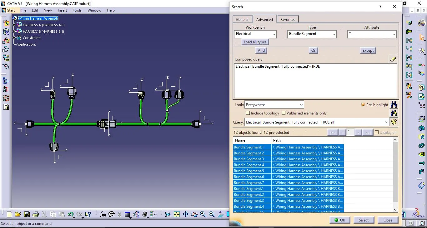
Bundle continuity in a wiring harness assembly is to check a seamless and unbroken electrical connection throughout the entire layout of the bundled wires. It helps to ensure that there are no interruptions or discontinuities in the electrical lines within the harness. Checking bundle continuity involves verifying that all wires within the harness are properly connected, with no breaks or disruptions, contributing to the overall functionality and reliability of the electrical system.
1) Harness A:
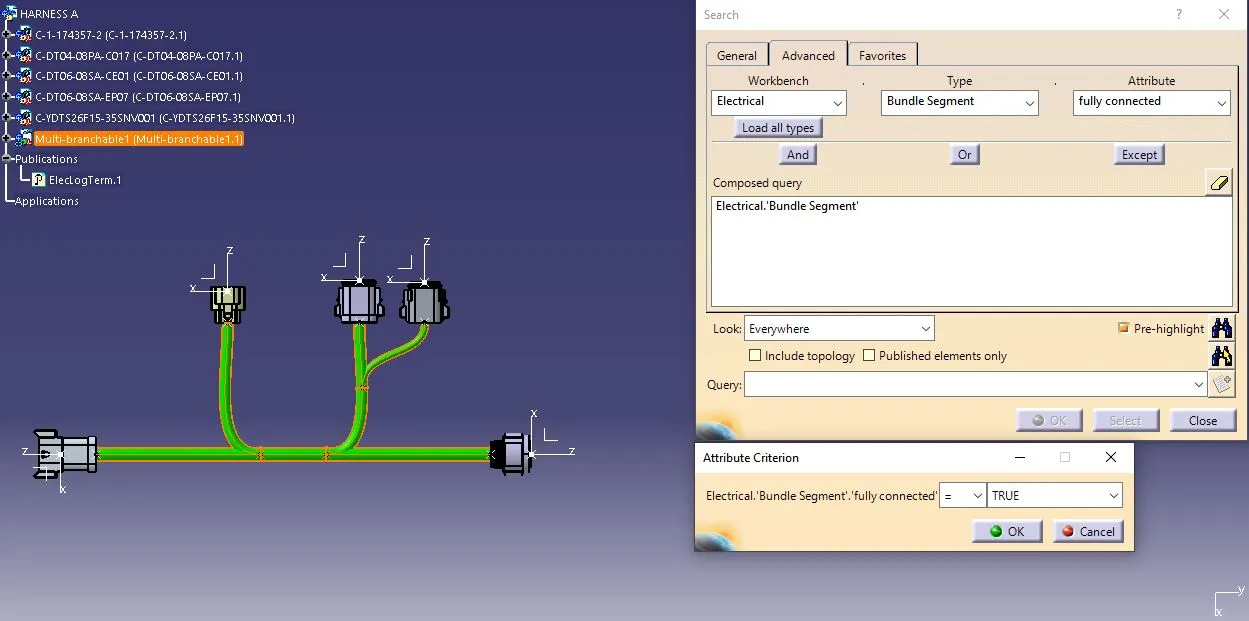
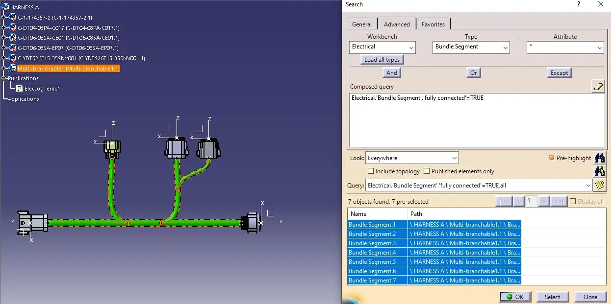
2) Harness B:
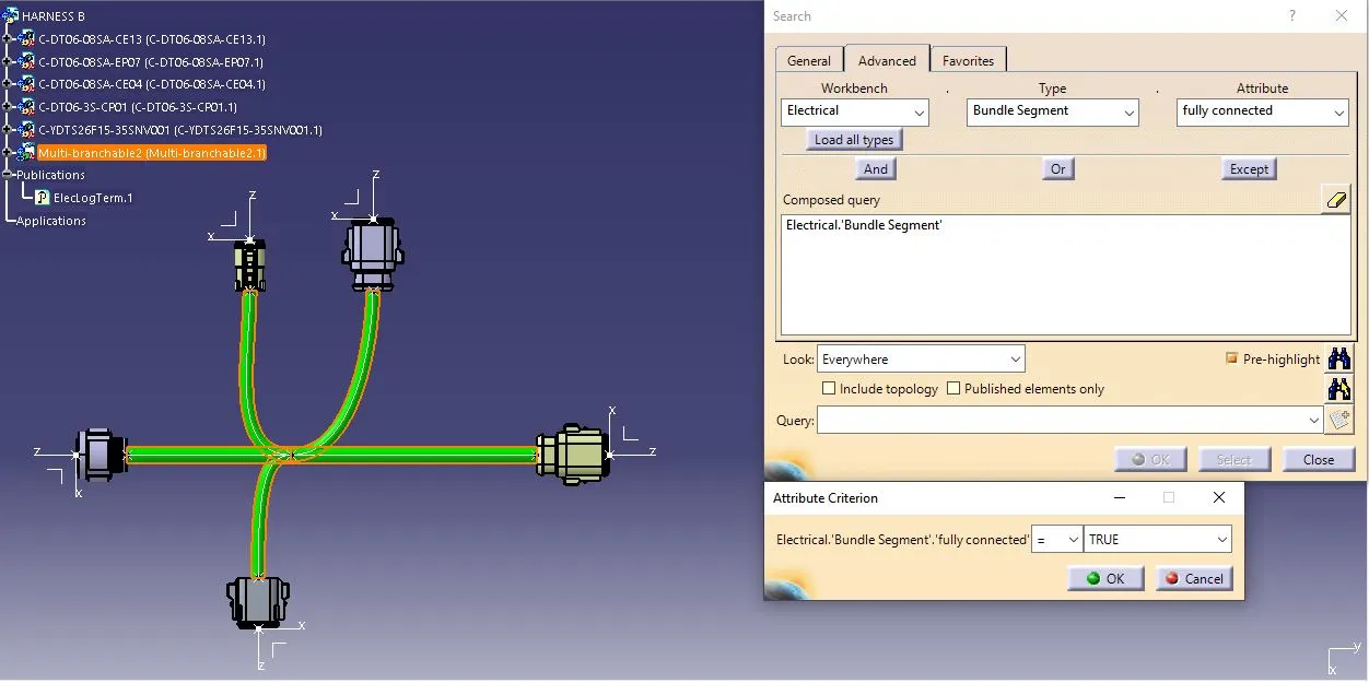
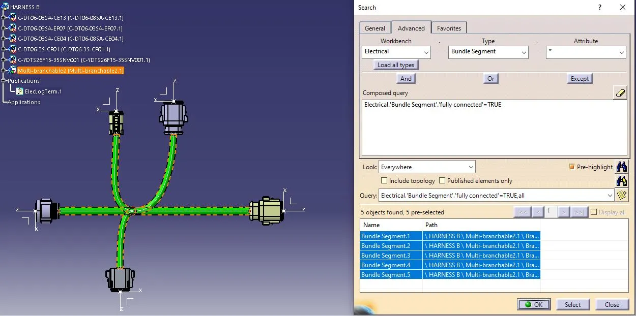
3) Wiring Harness Assembly:
Switch from Electrical Harness Assembly Workbench to Electrical Assembly Design Workbench
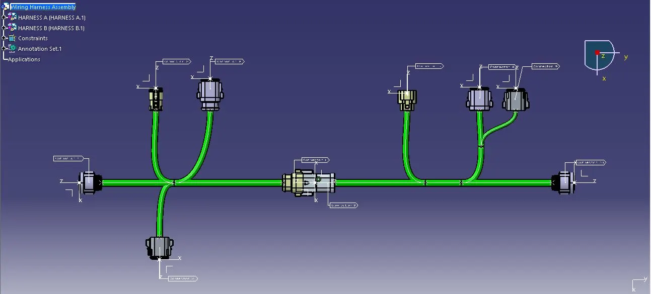
STEP-15: Connector Annotation
Connector annotation in electrical assembly design means adding labels or identifiers to connectors to describe their purpose, making it easier to understand and document the assembly.
STEP-16: Bundle Warning Check
A bundle warning check helps to prevent problems such as wires intersecting with each other, improper spacing, or violations of design rules that could lead to performance issues or manufacturing difficulties. Resolving any identified warnings during this check ensures that the final design adheres to design standards and minimizes the risk of electrical or assembly issues.
In Catia V5, the bundle warning is indicated in various forms:
1) Highlights with a yellow indication mark on the Multi-branchable in the Tree Structure
2) Highlights with a red sign in the computed bend radius in the branch definition and the branch segment line are also shown in red colour.
Switch from Electrical Harness Assembly Workbench to Mechanical Assembly Design Workbench
STEP-17: CATIA Part Generation
Generally, the wiring harness assembly consists of many connectors, clips, backshells, wire bundles and protective covers which are interlinked from various part files and catalogues. While sharing the wiring harness assembly file and its associated file, there are some possibilities for breakage of links between the assembly and the interlinked ones. To avoid that the entire wiring harness assembly is converted to a CATPart by following the navigation path - Tools > Generate CATPart from Product
STEP-18: Conversion to .igs Format
Once the CATPart is generated, save it either in .igs or .stp format so that it can opened and viewed in other CAD softwares.
CONCLUSION:
Thus, the given wiring harness layout is routed with the given connectors by assuming the harness bundle diameters. After routing, tasks included checking bundle continuity, adding connector annotations, examining bundle warnings, generating a CATIA Part, and converting it to the .igs format were completed. On successful completion of these tasks demonstrated proficiency in harness design and adherence to design best practices.