Wiring harness design in CATIA V5 - 3D modeling Week 5 & 6 Challenge
AIM
To Route the given two electrical harness layout and interconnect them as a single harness assembly. Also check the bundle continuity, and bundle warnings and then provide annotations for the final harness assembly.
GIVEN,
Layout of Harness B and Harness A
Steps to be followed:
1. Download connectors 3D data from given folder
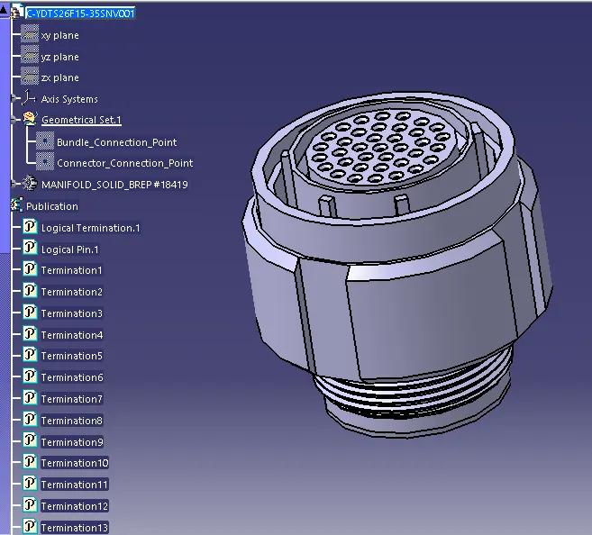
2. Converting the Mechanical part into the Electrical part for that I had followed the following steps.
Connector_1
Connector_2
Connector_3
Connector_4
Connector_5
Connector_6
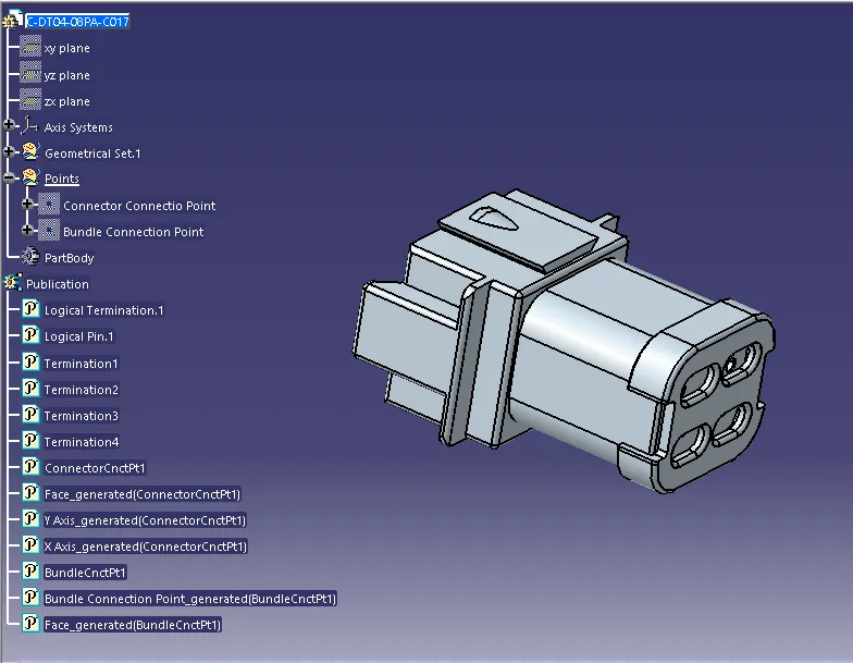
Connector_7
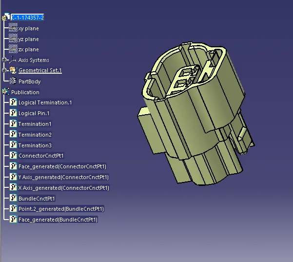
Connector_8
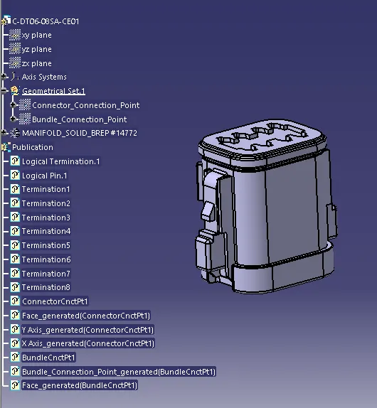
Connector_9
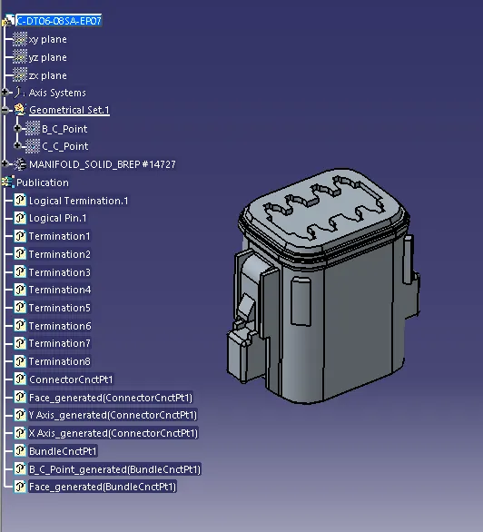
Connector_10
3.
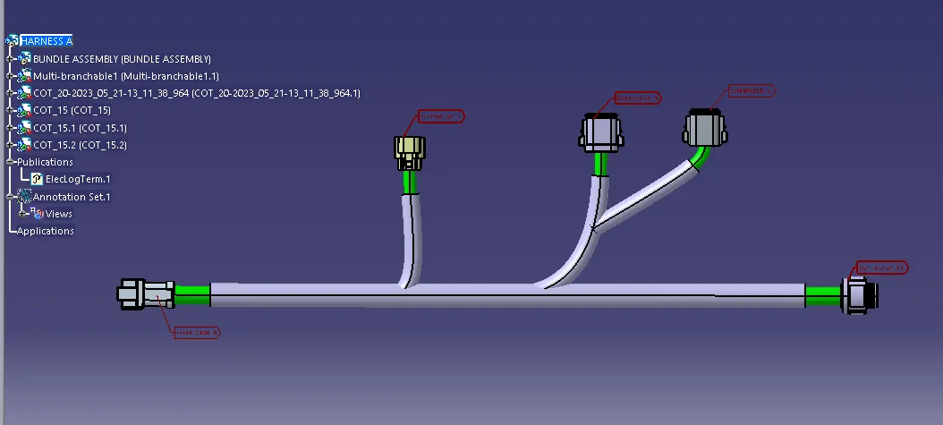
HARNESS A
After all connectors are defined and routed using the electrical workbench.
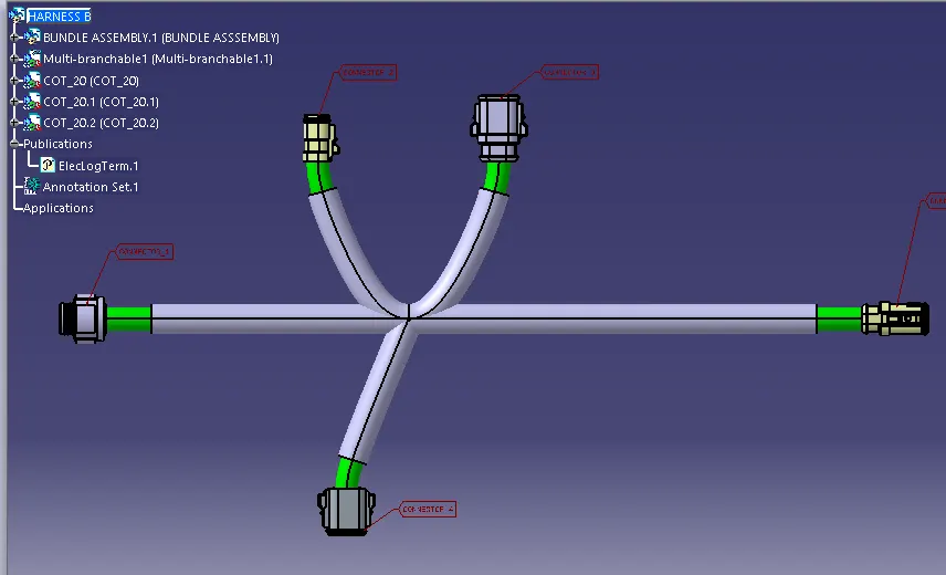
HARNESS B
After all connectors are defined and routed using the electrical workbench.
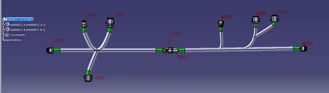
HARNESS ASSEMBLY
Connecting the Harness A & Harness B electricaly using the Electrical Assembly Design Workbench
4. CONTINUITY CHECK
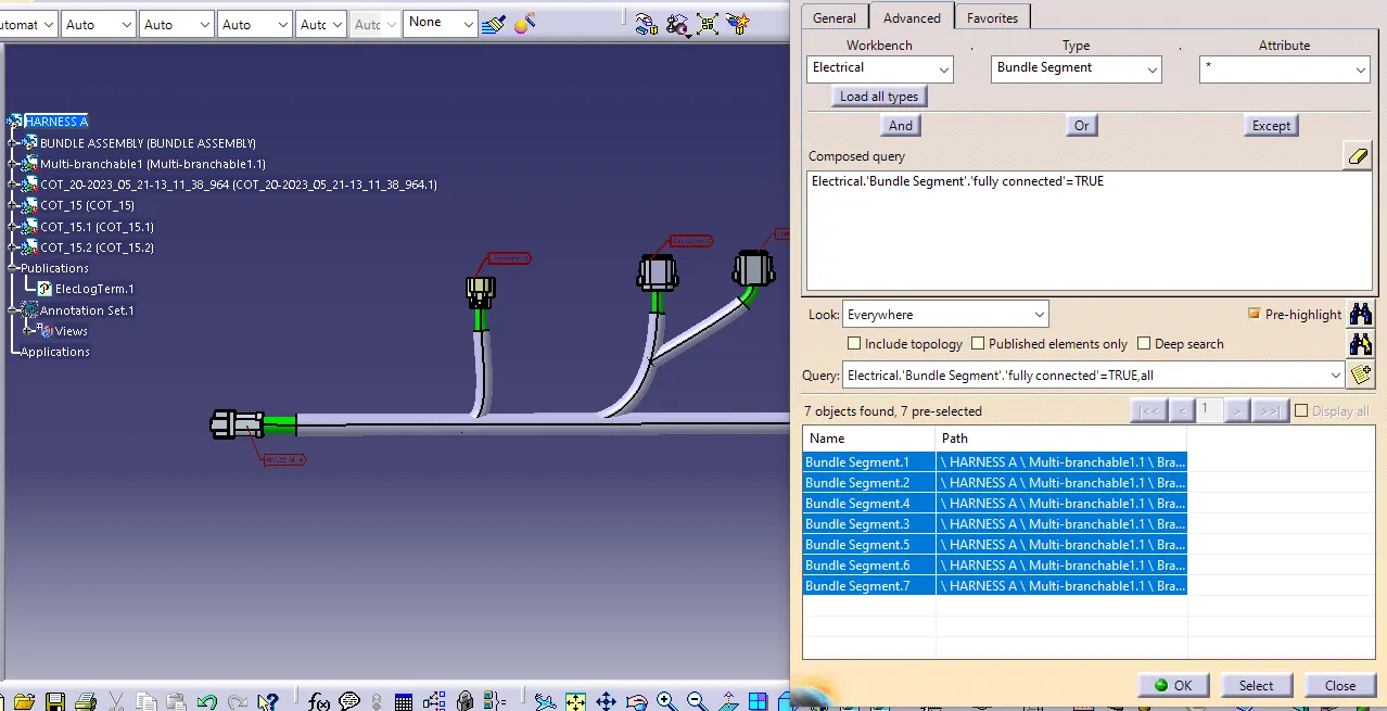
After Harness A and Harness B are created the next step is to check the bundle continuity.
For Harness A
For Harness B
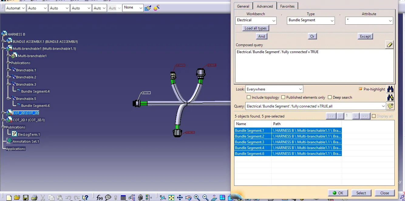
All the bundle segments in Harness A and Harness B will be displayed showing that there is bundle continuity in Harness A and Harness B.
5. ANNOTATION
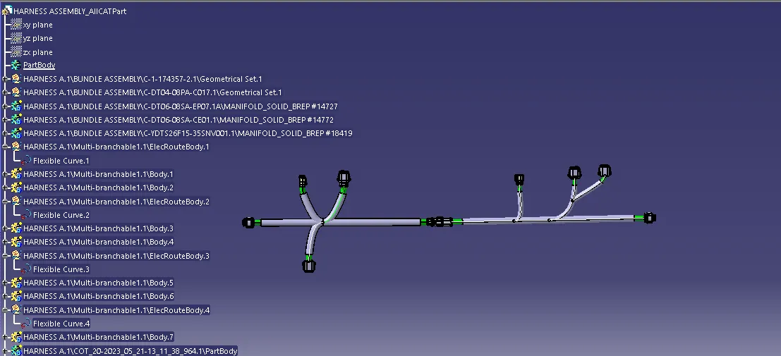
6. Generated CAT.part of harness assembly and converted in to igs format.
CONCLUSION
Routing of the two electrical harnesses was accomplished according to the provided layout. The interconnection between the harnesses was established to form a single harness assembly. Both harnesses were carefully inspected and any issues with bundle warnings and continuity were rectified. Finally, annotations were added to all the connectors and the final harness assembly file was converted into IGS format.