Wiring harness design in CATIA V5 - 3D modeling Week 5 & 6 Challenge
WIRING ASSEMBLY ROUTING
Objective
The project aims to explore and comprehend the given harness layout. By adhering to layout and design guidelines, two distinct wiring harness routing sets are to be developed and subsequently interconnected. The integration will be accomplished by incorporating them into a new product file utilizing the CATIA V5 tool.
Overview
Design and Routing of Wiring Harnesses
Wire harnesses represent an amalgamation of wires bundled together to construct a comprehensive wiring system. Ranging from simplistic point-to-point configurations to intricate arrangements involving hundreds of wires, multi-conductor cables, and welded components, wire harnesses serve to transmit power and diverse types of data. These designs are highly adaptable, tailored to specific applications that may involve concealment, fitting within constrained spaces, or complying with other spatial constraints. Precision in measurements, considering the environment, power requirements, and lengths, is crucial during design to avert expensive errors and guarantee the safety and proper functionality of the end product.
A wiring harness routing structure comprises a wiring harness routing member designed for attachment to a vehicle body and a protector that accommodates and secures the wiring harness. The protector features a recess shape, open in one direction in a sectional view. At least one of the wiring harness routing members and the protector incorporates a fixing mechanism, securing the protector to the wiring harness routing member. Integration of the protector and the wiring harness routing member is achieved through this fixing mechanism.
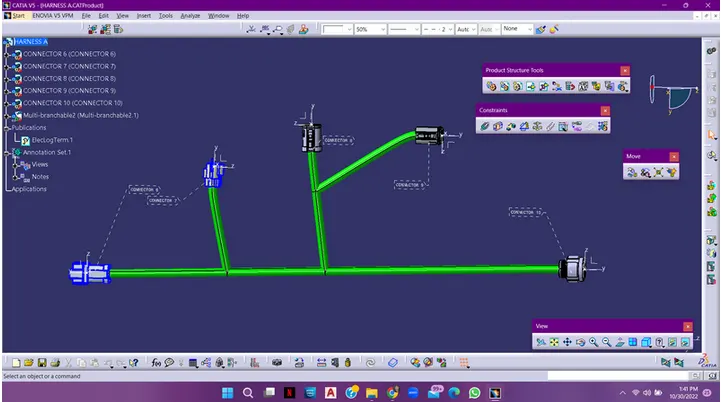
INPUT WIRING HARNESS CONFIGURATION
PROCEDURE
Connector - Mechanical to Electrical Transition
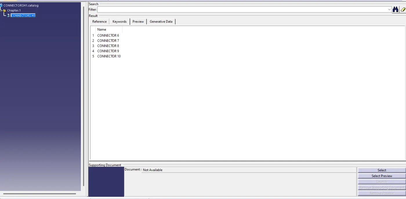
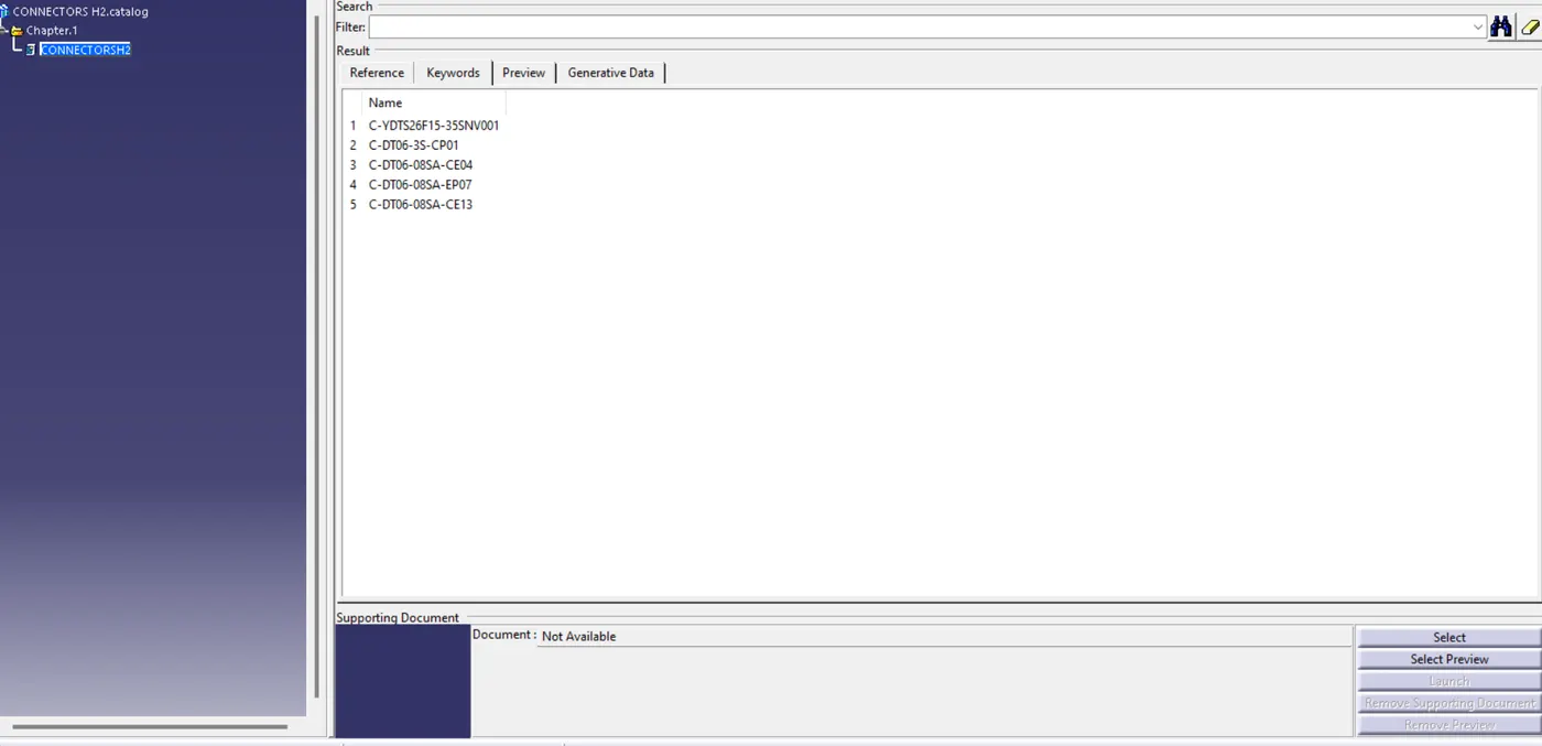
- Download neutral data files (STEP/IGS) of connectors from the designated source (TE Connectivity website) and open them in the CATIA part workbench.
- Identify connector connection point faces, bundle connection point faces, and the mechanically locking sides of the connectors.
- Create geometries such as center points and axes on the connector connection point, ensuring consistency with the orientation of the locking mechanism.
- Switch to the electrical part design workbench, defining the model as an electrical connector part using the 'define connector' command.
- Define the connector connection point and bundle connection point using appropriate faces and orientations.
- Repeat the process for all connectors, converting them into electrical parts.
- Create a new product file for wiring harness assembly, adding relevant components and converting the geometrical bundle assembly file into an electrical bundle.
Assembly and Routing of Wiring Harness
- Create the main product file for the wiring harness assembly and new product files for geometrical bundle assembly and electrical bundle circuit.
- Position connectors in the geometrical bundle assembly using commands in the mechanical assembly workbench.
- Switch to the electrical harness assembly workbench, activate the geometrical bundle command, and convert the geometrical bundle assembly into an electrical assembly.
- Apply routing using the multi-branchable document command, adjusting connector diameter, bend radius ratio, build mode, and utilizing routing objects options.
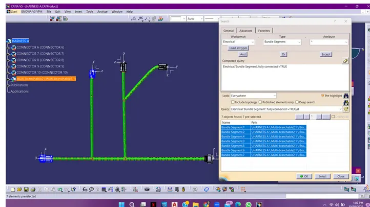
- Use multi-branch routing, add or split branches as needed, ensuring proper bundle connections.
- Check for bundle continuity in the wiring harness assembly under the edit command.
- Add annotations in the mechanical assembly workbench, defining planes and providing notes or functional commands.
- Check for bundle warnings and resolve errors related to inappropriate bend radii.
- Connect the two sets of wiring harness assemblies (A & B) in a new product file using the connect electrical device command.
Final Steps
- Create a CAT part of the harness assembly and convert it into a neutral data file (.igs format) in the mechanical assembly workbench. Neutral CAD file formats facilitate interoperability between different CAD software.