Advance Meshing of Ford for External Aerodynamics
Aim:- To Perform Geometry clean-up, Surface Meshing, and Volumetric mesh of Ford Car For external Aerodynamics.
Procedure:- Procedure for the geometry clean-up of the Ford car model is as follows.
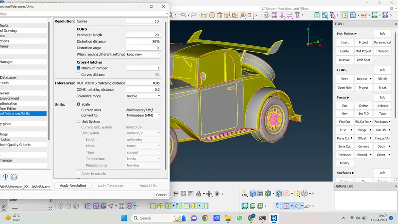
1. open the car model geometry in ANSA software. Then first check units and resolution.
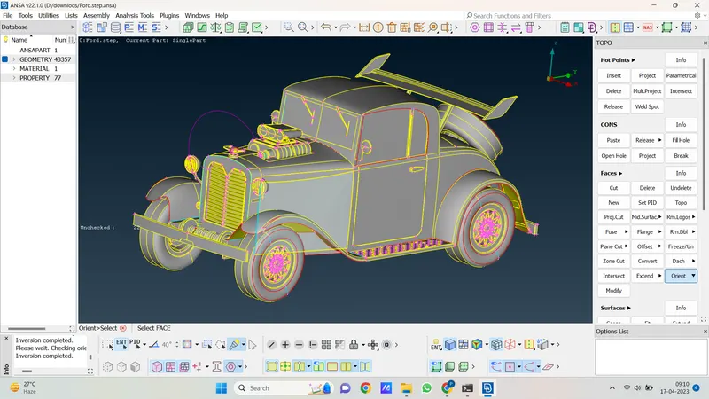
2. then orient the geometry as follows.
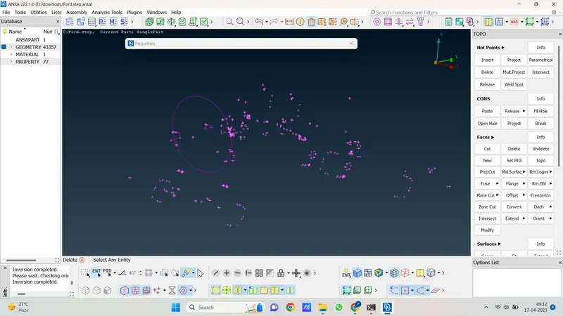
3. Now we hide all faces and geometry and delete the remaining unwanted faces and geometry which we don't require.
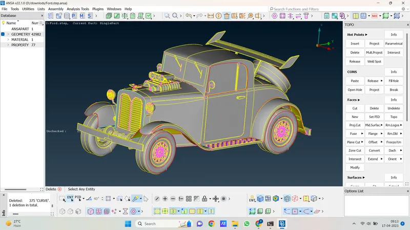
4. we see the geometry of the car model is too complex and large to solve it the easy way we delete half geometry and solve the error of half of the geometry and then mirror it. But for that, we first hide non-symmetry geometry because we only delete that half of geometry which is symmetry.
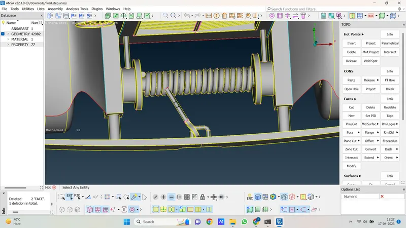
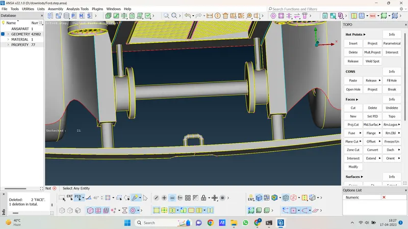
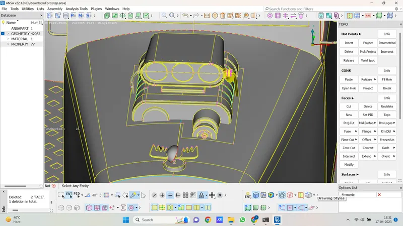
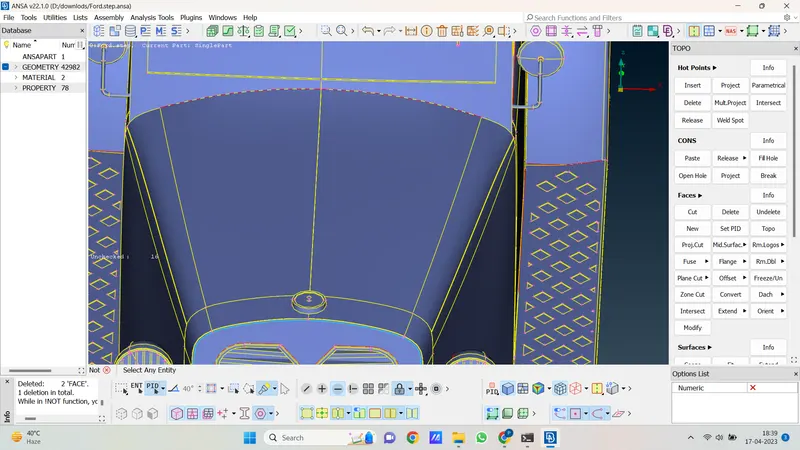
5. we hide some geometry as follows.
Rope and hook
Logo and engine
Stepni tyre
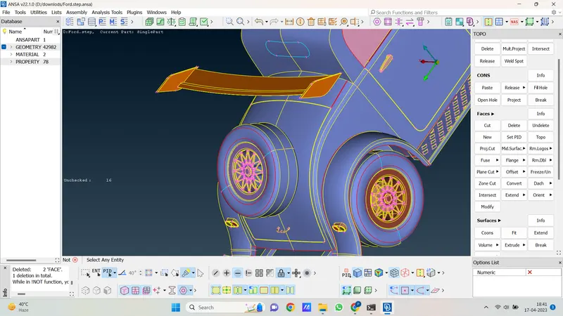
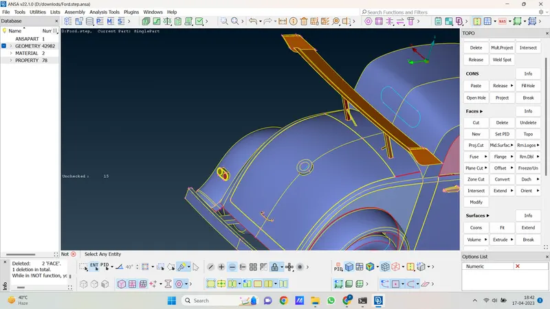
6. there is some non-symmetry geometry inside the car so we isolate them to save them separately and delete them after clearing the whole car geometry then merge this deleted geometry into actual geometry.
7. so we isolate seat and steering geometry which is not symmetry and then we save it and delete it from the main geometry.
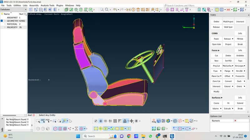
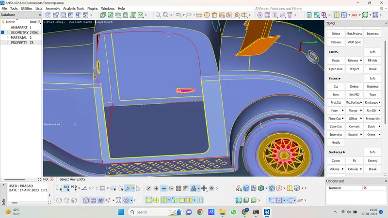
8. now remaining all geometry is symmetric so let's cut the half car with the use of the cut plane option.
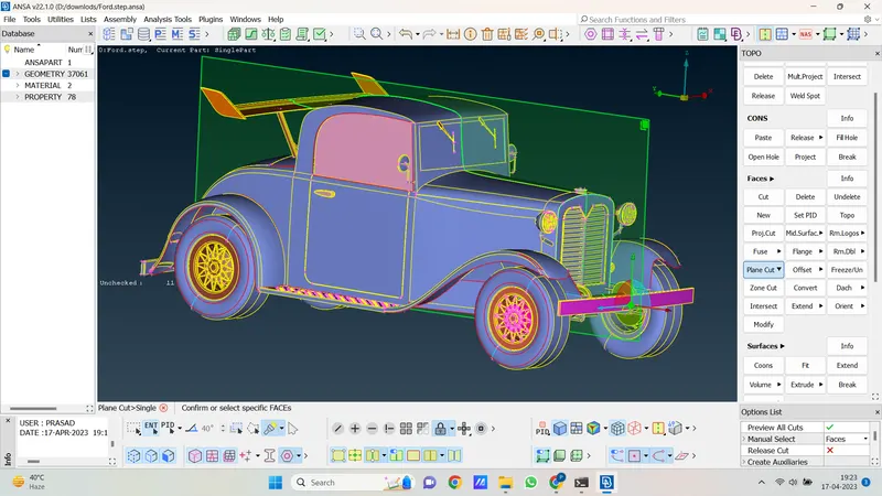
9. now hear cut plane create perfectly now delete half car model as below.
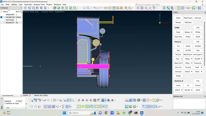
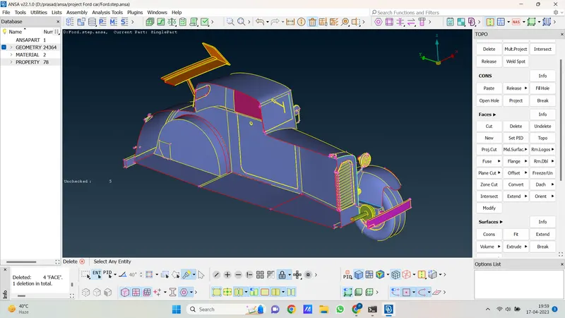
10. Geometry is not looking perfect somewhere, so we change the resolution to 10 mm.
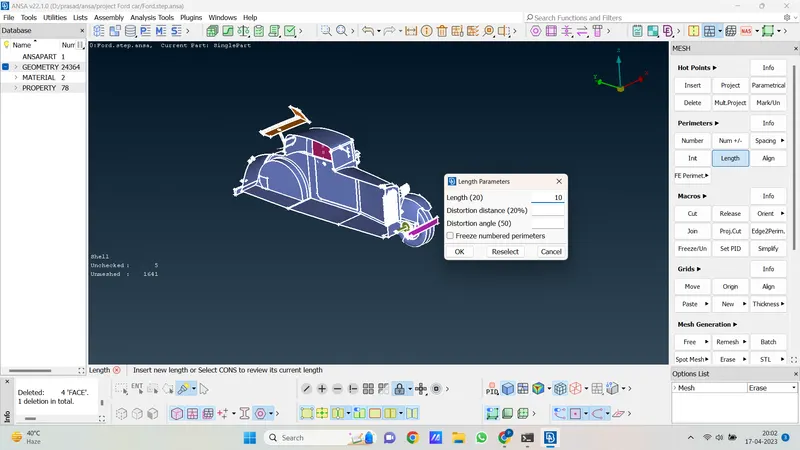
10. now we go for a geometry check and see how many errors are in geometry. And solve them one by one.
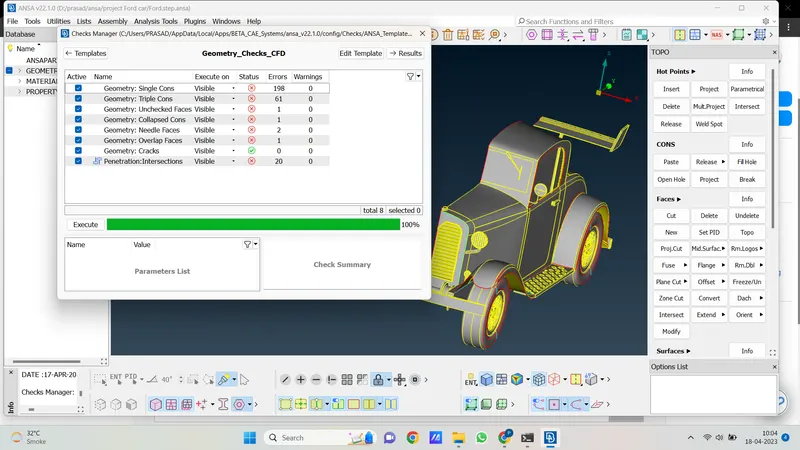
11. There are too many errors in geometry, so let's solve them one by one.
12. first we go with tyre, let's isolate tyre and solve the error.
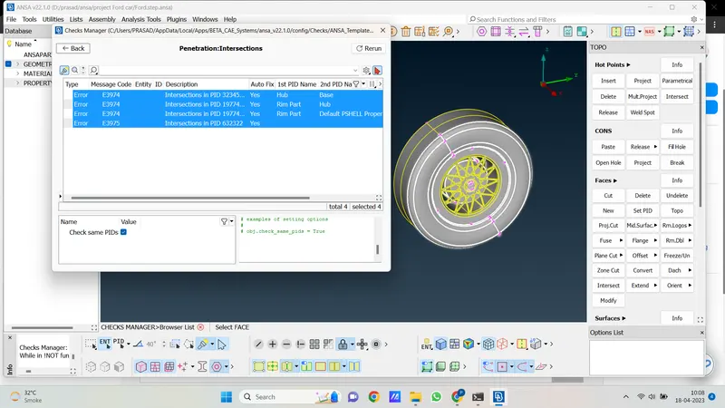
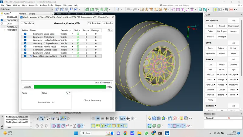
13. Now we have resolved all errors in tyre geometry .so there are 4 tyres in geometry so we deleted the other tyre and copy paste this errorless tire on that place.
12. for copy-paste tyres we want to create the point at the center of the tyre as follows.
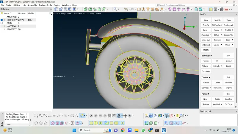
13. now let's delete the rear tyre and with the help of the transfer option copy the front tyre to the rear side.
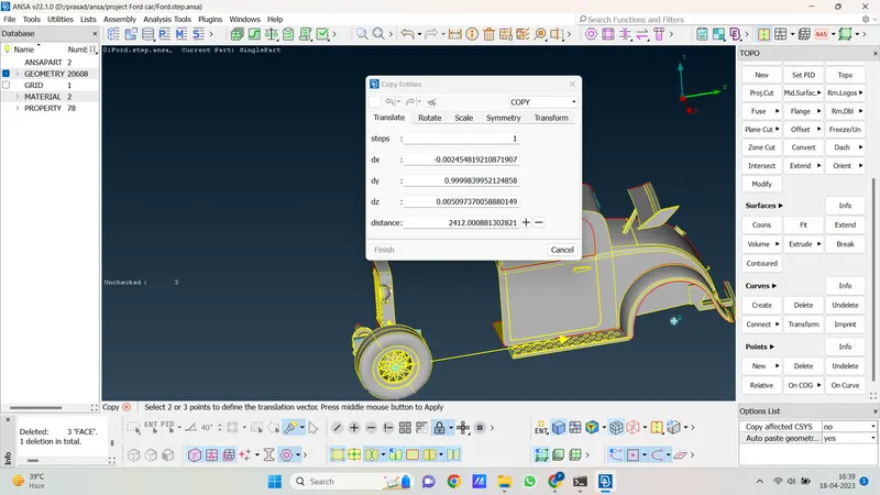
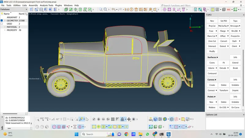
14. hear we successfully copy our front tyre to the rear side.
15. now we isolate grills and start to work on them and solve all errors.
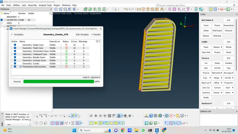
16. hear we see there are some single cones, triple cones and intersections there let's resolve it and make geometry errorless.
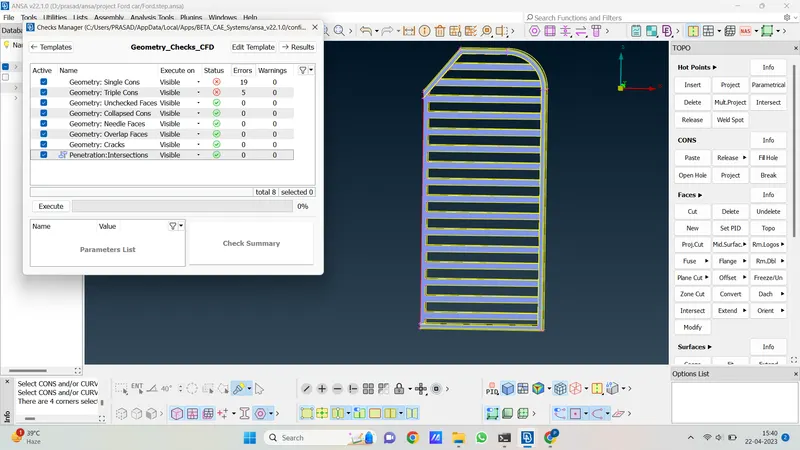
17. as per the above picture we solve errors in grills there is some triple cone which is avoidable and some single cone that is due to half geometry.
18. now let's isolate the spoiler and go for a geometry check.
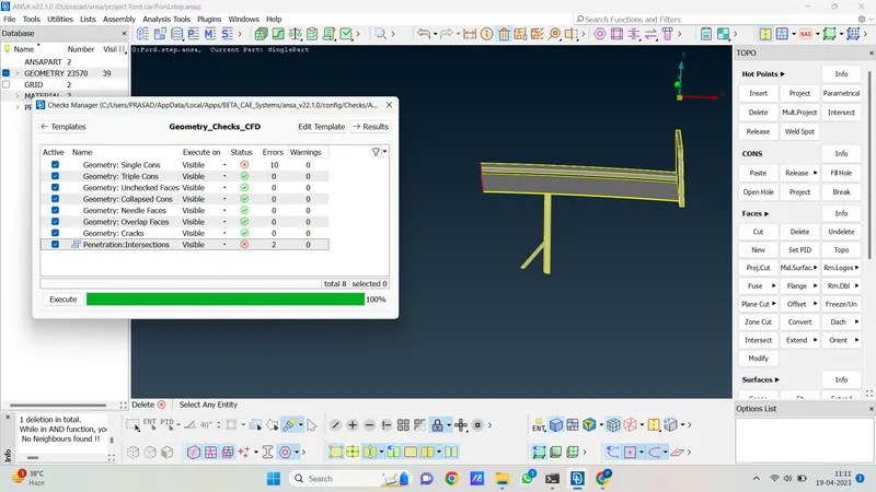
19. as per the above snap there is some error let's solve it as follow.
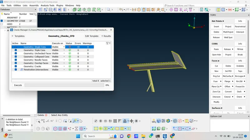
20. now we isolate outer body geometry and check geometry error.
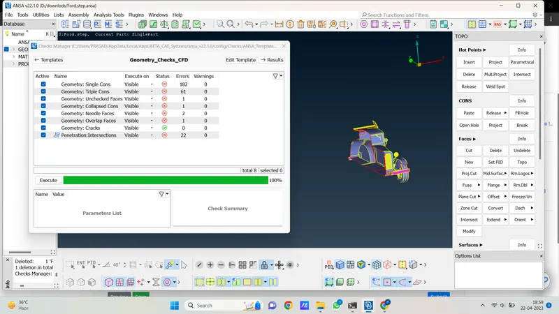
21. so there are so many errors in the outer body and the outer body consists of a headlight, mirror, window, handle, etc. so were clear one by one and solve all errors.
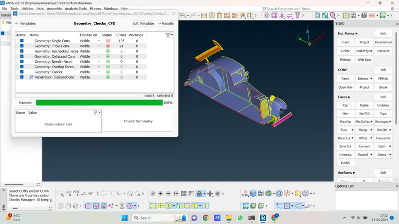
22. now hear we have resolved all errors in geometry. but we see some triple cones are avoidable and also some single cones which is due to half geometry. as like that outer casing is done now we mirror half part to the opposite side and see what our geometry looks like.
23. for mirror we use the transform option and in that, we go to copy an entity and ten select entity and copy its opposite side and our geometry will look as follow.
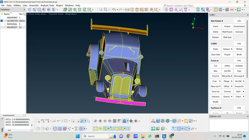
24. so here geometry is mirrored successfully. Now we go for a geometry check and see if there is any error coming after mirroring it.
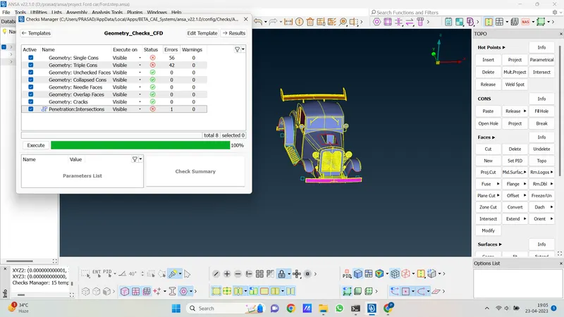
25. after checking geometry 1 intersection is coming which is present in grill geometry and front bumper let's resolve it.
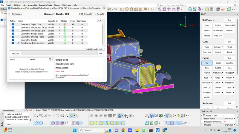
26. now hear we resolve errors in car geometry now we unhide the unsymmetric geometry that we hide before. and then isolate them one by one and then go for a geometry check and resolve their error.
27. let's isolate the engine and check the error in engine geometry.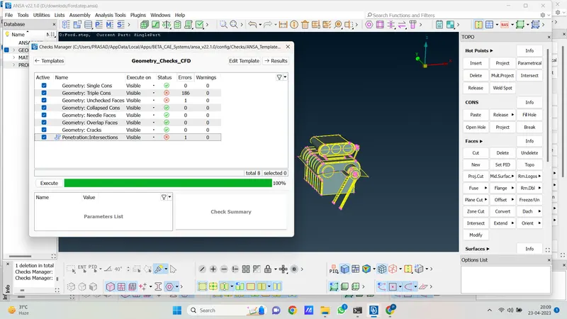
28. hear there are so many errors in geometry let's resolve it and see.
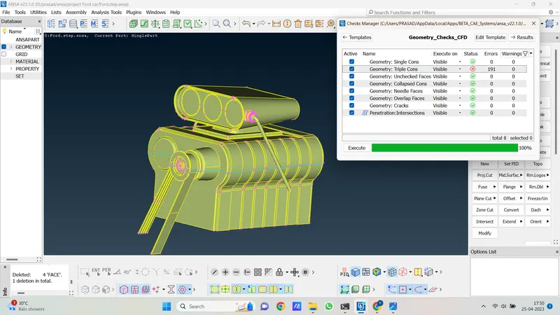
29. so hear we clear all inter-section single cones, and triple cones errors in geometry. but we see some triple cones are avoidable because they create due to contact with a bumper.
30. now we isolate the Stepney tyre geometry and check the error in that.
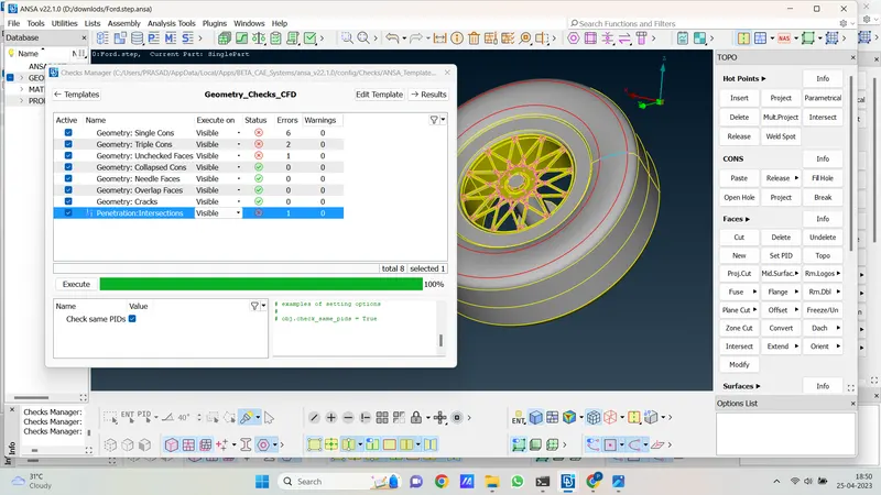
31. so hear also some triple cone single cone and some intersection lets clear it and make geometry errorless.
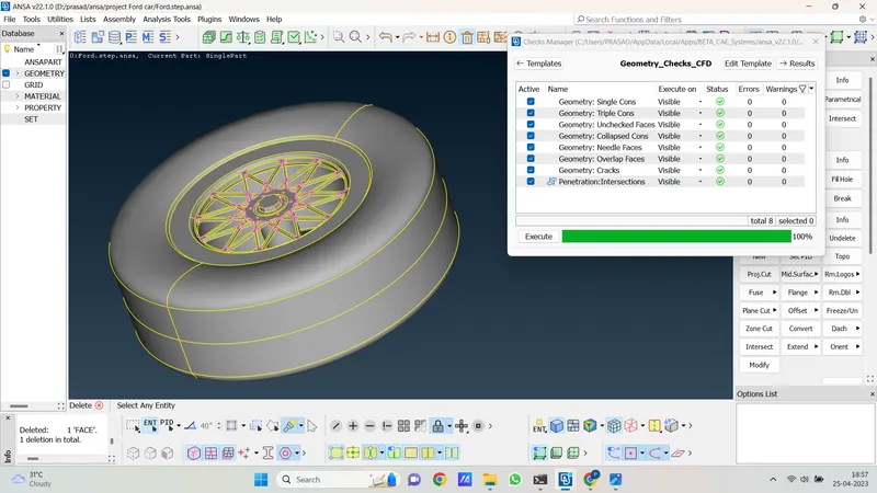
32. as the above picture we see now there are no errors present in geometry.
33. now we merge the seat and speedo meter in our car geometry.
34. for merge seat and speedo meter we go to file and open the merge option as below.
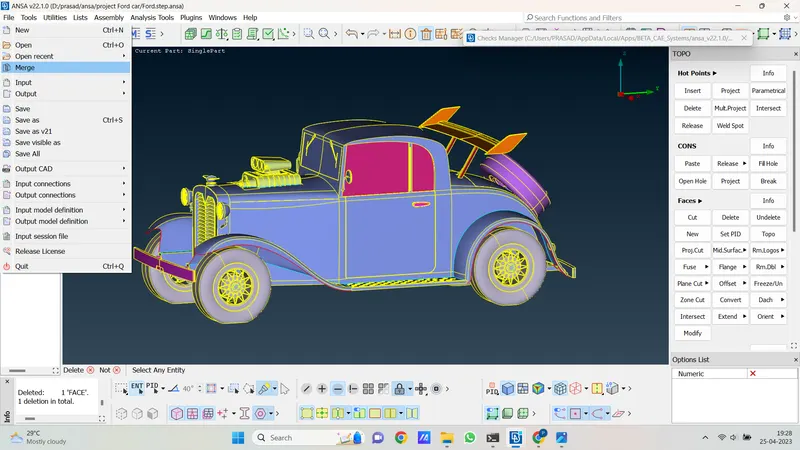
35. after opening merge new page will open In that find our seat geometry and open it
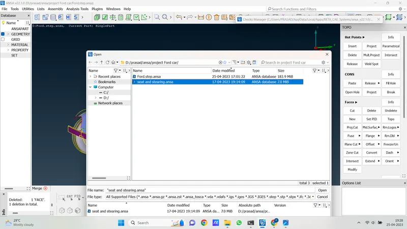
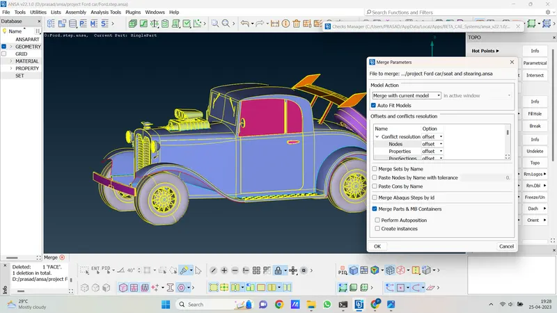
36. After opening the geometry file again a new page will open and there we select merge with the current model and then click on ok after that geometry of the seat and speedometer merge successfully in our geometry. as follows.
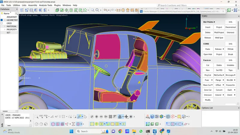
37. now hear we isolate seat and meter geometry and go for geometry check and see what errors are coming.
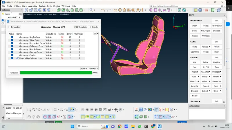
38. so there are too many single cones triple cones and intersection cones are there. let's clear all errors and make geometry errorless as follows.
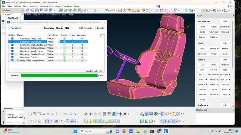
39. so here we clear all geometry now once again we go for geometry check for the entire car geometry as follows.
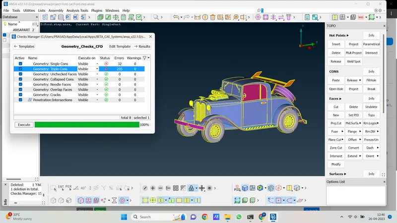
40. As above picture we see there are no errors we see only some triple cones and single cons are there and these errors are avoidable we can ignore these errors.
41. so the geometry cleanup of Ford car models is done. now we define PID for all element as follow.
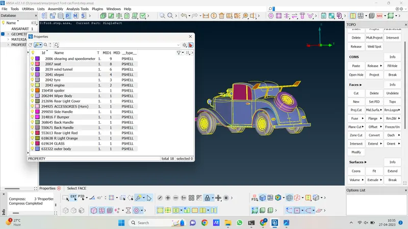
The procedure for making a wind tunnel is as follows.
1. for creating a wind tunnel there is some standard dimension. as follows.
if the car length is x and the car height is h then the standard dimension is.
the front wall is 3x from starting point of the car.
the back wall is 6x from the ending point of the car
upper wall of the wind tunnel is 4h from the top point of the car.
side width of the wind tunnel is 2000mm from the side point of the car.
2. let's calculate our car's height and length with the help of the measure option. after measuring dimensions we understand our car's length is 3421mm and height is 1320mm.
3. we start from the base tunnel wall. with the help of points, we create a plane.
4. so first we create the point at the center of the car with the help of on COG point option in that we select the point option as follows.
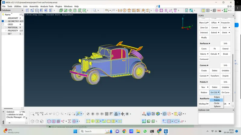
5. after that we select all tyre center point that we created before for copy paste tyre. after selecting 4point then click the middle button and the center point is created as shown as follows picture.
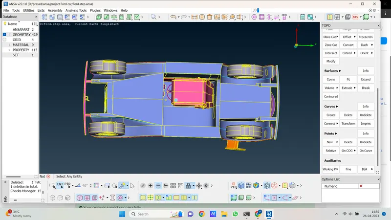
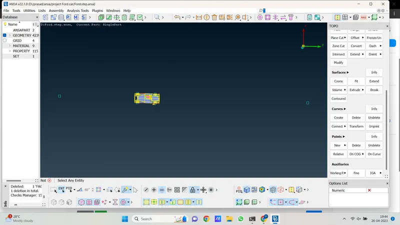
6. now we create the point at a distance of 3x from the center to the front side. where we create the front tunnel wall also add our half measurement of the car because the point lies in the center. so half the measurement of the car is 1620mm and the car's length is 3421mm so the total length to create the point at the front is 3421*3+1620= 11883mm. we create a point from a center point to the front side at a 11883mm distance. also like that for the back side tunnel wall the standard dimension is 6x plus half car measurement. so we create a backside point at a 22146mm distance. point is shown as follows
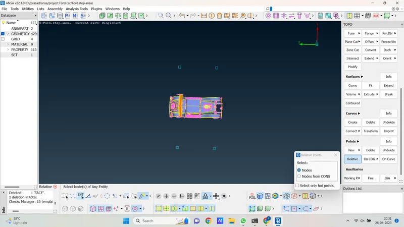
7. now we move the points which are present at the center of all tyres towards the side at a distance of 2000mm as shown in the image below.
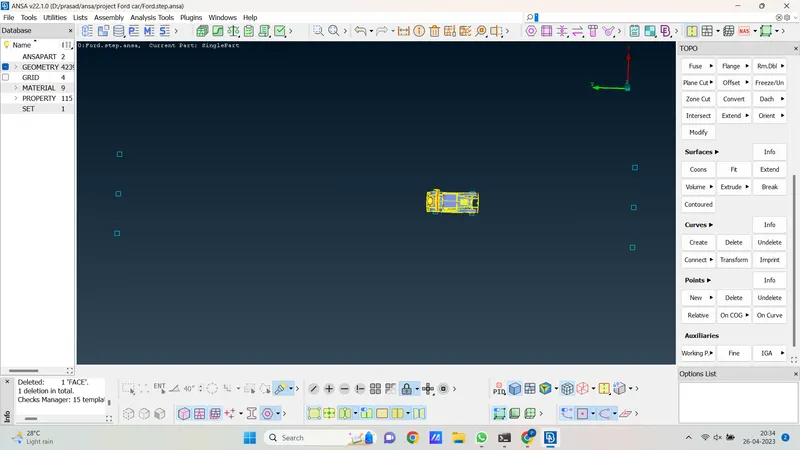
8. now we move the front 2 tyre point toward the front point which we create at the place of the front wind tunnel also move back 2 points toward.
back side wind tunnel point position is shown as follows.
9. now we create a curve from one point to another and then create a plane.
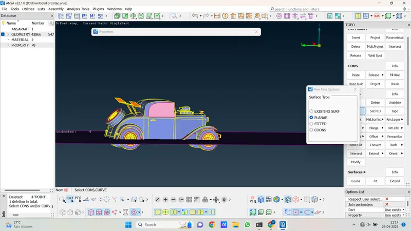
10. now we move this plane toward tyre end and then give tyre crush of 10mm. for moving planes we use the transform option.
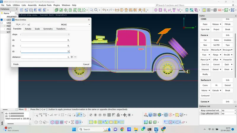
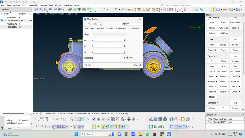
11. so here we create the base of the tunnel now we copy this plane and paste it upward at a distance of 6600mm which is the height of the top plane of a wind tunnel.
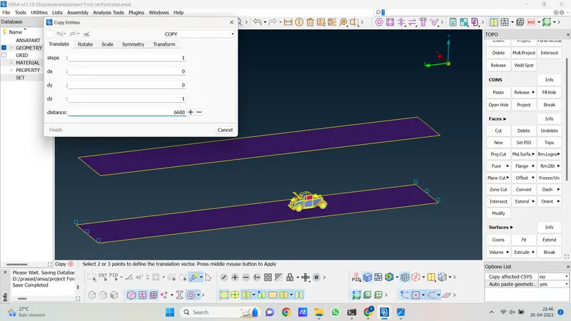
12. hear top and base plane of the wind tunnel are created now we close with all other edges. now our wind tunnel will look like as follow.
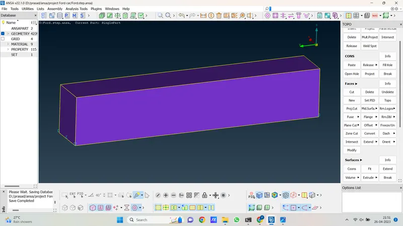
13. during creating the base plane we also give tyre crush of 10 mm now we delete tyre crush entity that comes out from the plane as like shown in the following images. To delete tyre entity that comes out from the plane we intersect the plane and tyre now we are able to delete that entity.
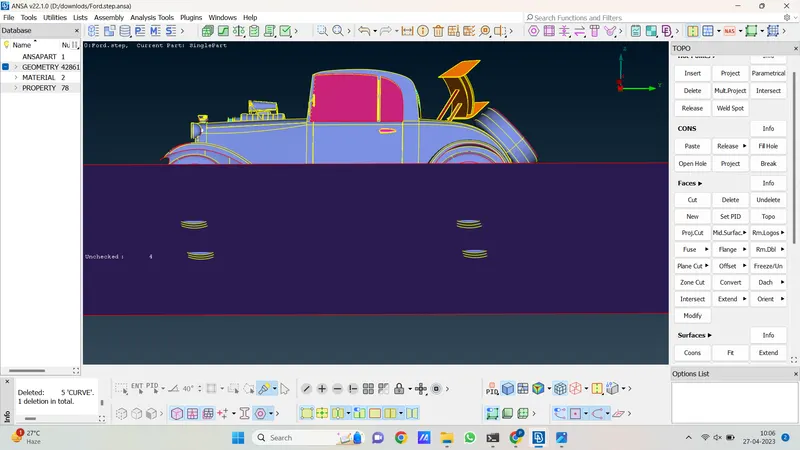
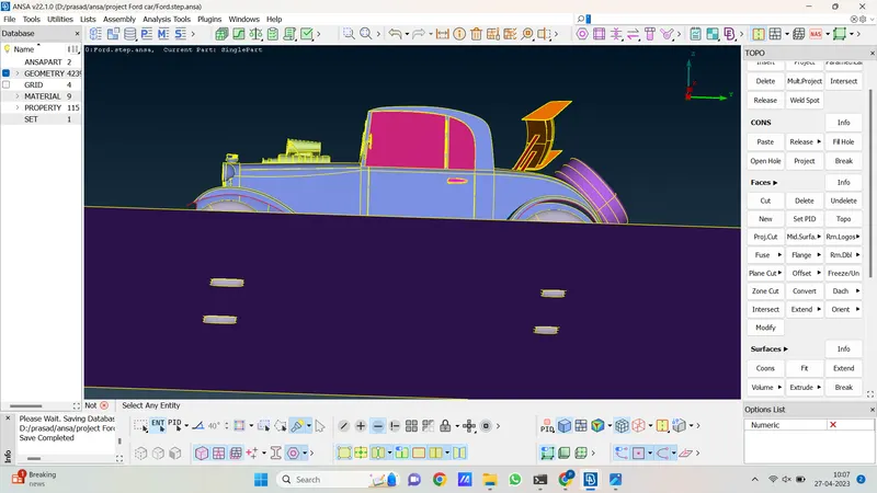
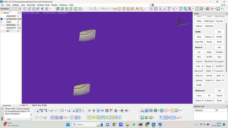
14. so hear we successfully create a wind tunnel and perform tyre crushing. now we go for further process which is surface meshing.
The procedure for surface meshing of the car and wind tunnel is as follows.
1. for surface meshing we go to the mesh module first.
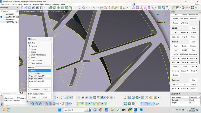
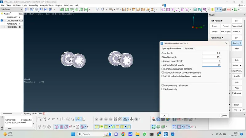
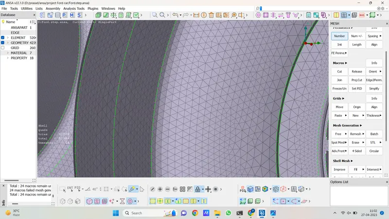
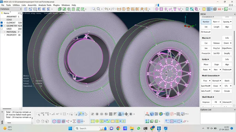
2. now we mesh all elements one by one with the help of PID so first we isolate tyre geometry and measure the smallest distance in that and decide the target length. so the smallest distance is 3 and we take the maximum distance as 10. as follows. so before mesh, we define parameters and macros. after that we select tria type mesh element which we use for the meshing hole car model. Then we mesh tyre geometry with the use of the adv. front meshing algorithm.
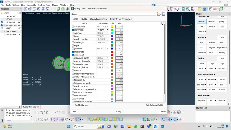
3. now we check the skewness mesh in tyre geometry. to active skewness first go to quality criteria then in that we select skewness and click on ok.
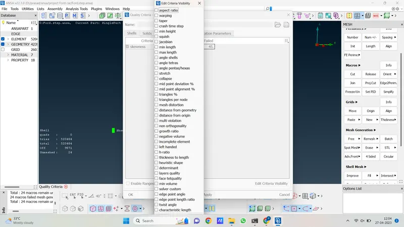
4. after that go to the quality criteria visibility option below and deselect all option
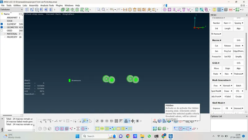
5. now active hidden drawing style then we can see skewness element.
6. now we see there are 24 unmeshed elements to mesh them apply free mesh after that now we solve the off element right click on the off element and go to improve and reshape the off element. after that, all of the elements are resolved if some are remaining then solve them manually with the help of the move option.
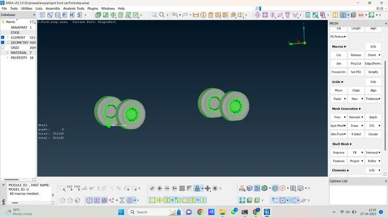
7. see the above image there is no unmeshed element also no off element we successfully mesh tyre geometry. now we follow as same as these all steps to mesh other PIDs one by one only the target length is different for different PID elements which we discover one by one.
8. now we isolate Back Handle, Rear Light Red, R Light Orange, Back Handle, Side Handle, ACCESSORIES (Horn), Rear Light Cover, Wiper Body, and car logo.
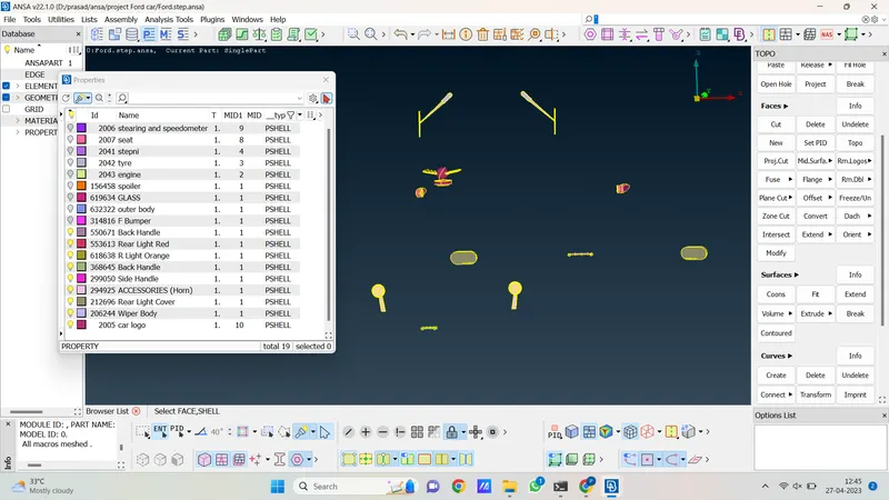
9. to mesh them we specify a minimum target length of 0.5 and a maximum target length 8. With the help of the CFD mesh algorithm, we mesh isolated geometry. after meshing we freeze the geometry.
10. now let's isolate the outer body, glass, and front bumper.
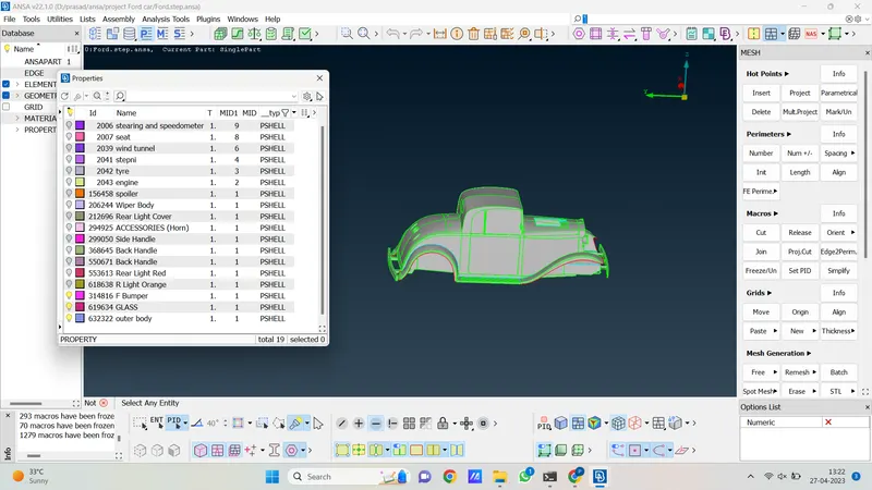
11. To mesh this geometry we specify a minimum of 2mm and a maximum of 15mm target length and to mesh them we use Adv. front mesh algorithm. as shown as follows.
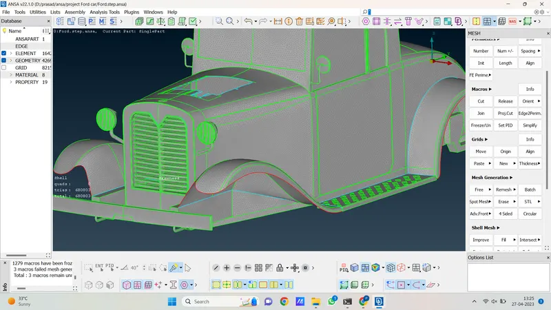
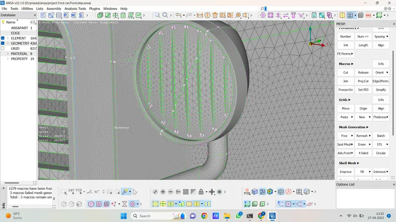
12. now we isolate engine PID and give a target length minimum of 0.5mm and a maximum of 10mm. and for meshing we use hear Adv. front algorithm.
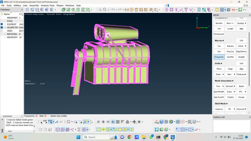
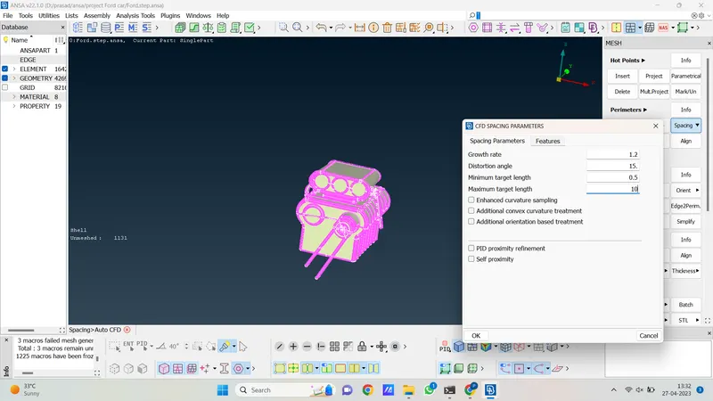
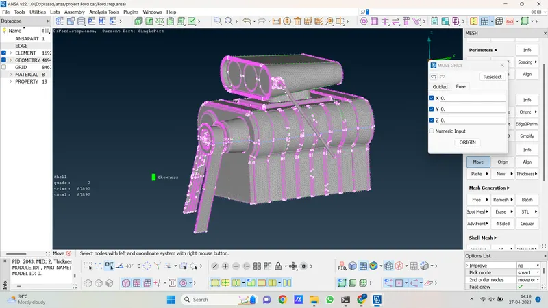
13. now there is no off element and also no unmeshed element.
14. let's isolate the seat, stepney, and spoiler and give a target length of 0.5mm minimum and 10mm maximum target length. and we mesh geometry with the use of Adv. front meshing algorithm.
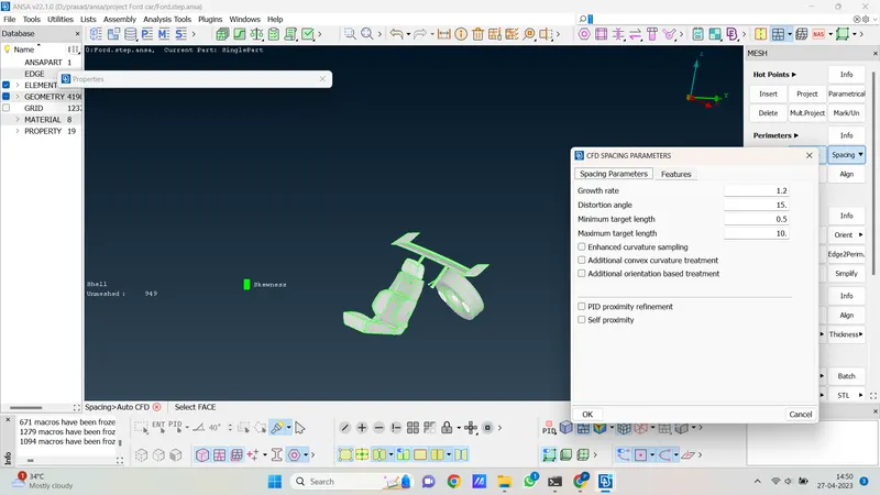
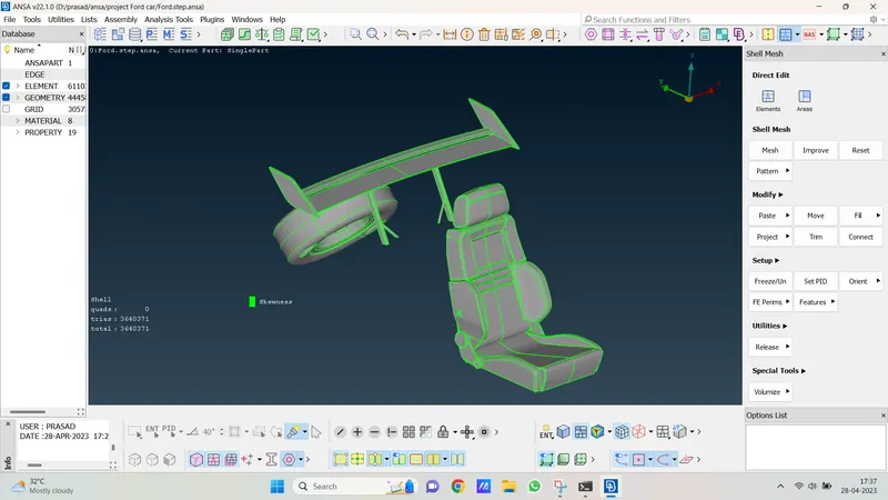
15. so as per the above picture we see there are no unmeshed or off-mesh elements. so we successfully mesh these geometries.
16. now that only steering and meter geometry are remaining let's isolate it and give a target length minimum of 0.5 and a maximum10mm as shown in follows. then we mesh geometry with the use of the CFD mesh algorithm.
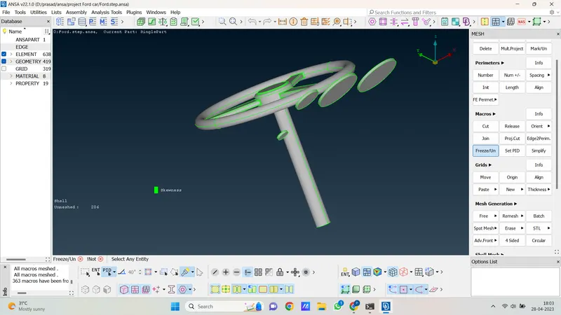
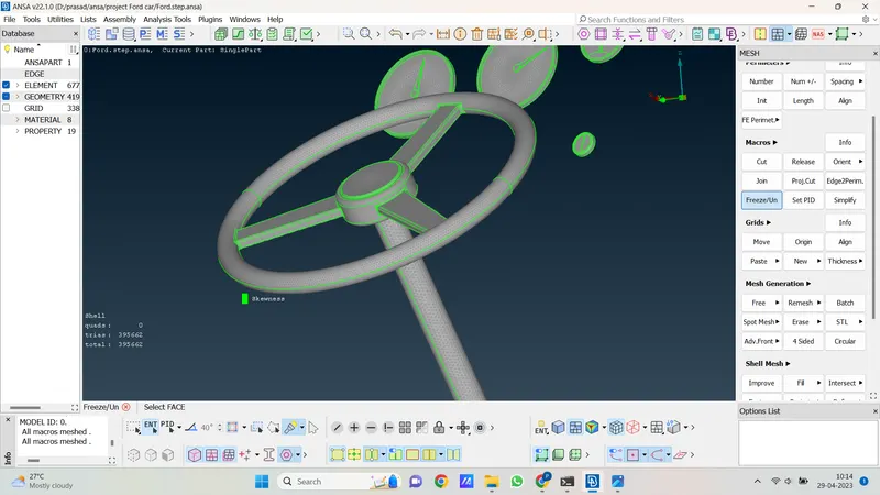
17. we see there is no unmeshed and off-mesh element present in geometry. now all part of the car model has meshed perfectly now let's isolate the car geometry and see how many unmeshed and off mesh element is present in the whole geometry.
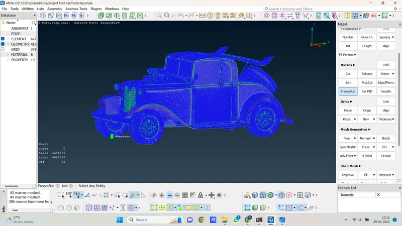
18. so here we see no unmeshed element are there but we see there is 85 off mesh element present in geometry and that much off element we can ignore it. because is all mesh elements we can ignore 10% off mesh elements.
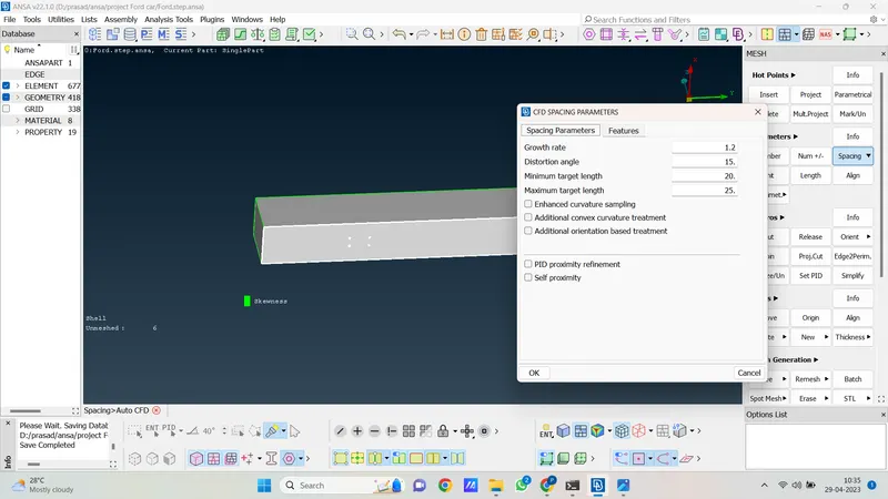
19. so after completing the geometry now we mesh the wind tunnel let's isolate the wind tunnel then we specify the target length to the bottom tunnel plane which is a minimum of 20mm and a maximum of 25mm.
20. after that we specify the target length of the remaining wind tunnel plane which is 10mm minimum and 150mm maximum.
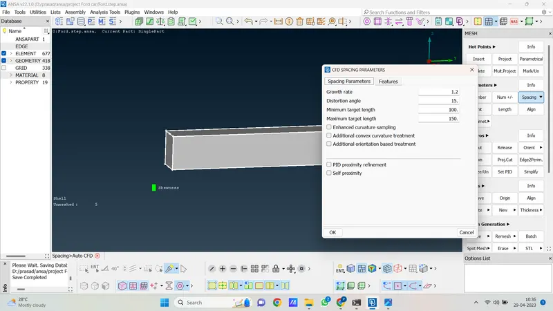
21. so we define the bottom plane as different target lengths because our car geometry is connected with the bottom surface also we require fine volumetric mesh close to car geometry.
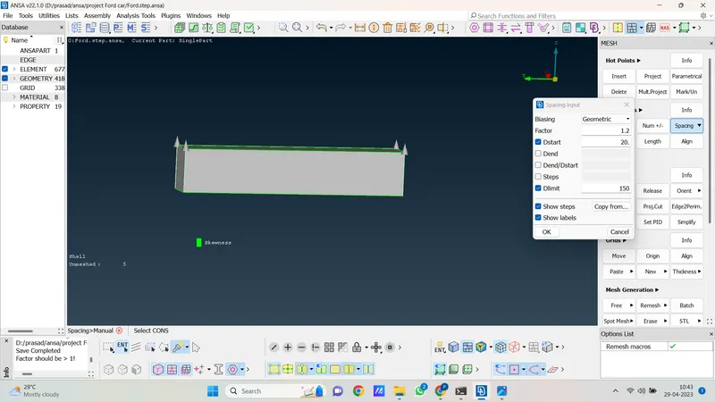
22. after that we have spacing geometry and give a growth factor of 1.2 and spacing geometry from bottom to top which is 20mm to 150mm as shown in the following picture.
23. after giving target length we now mesh wind tunnel with the use of Adv. front algorithm.
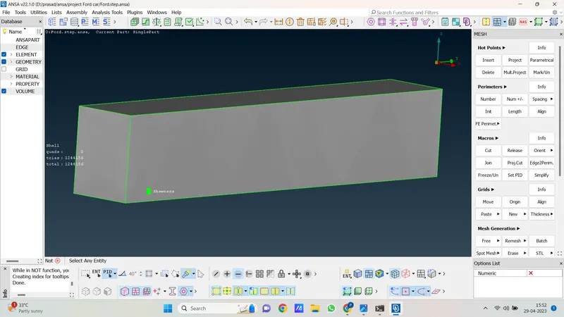
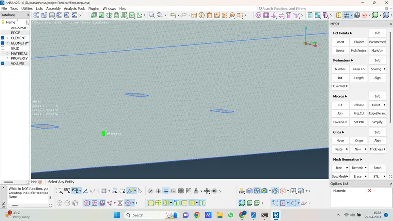
24. so now we mesh all geometry and hear surface mesh is done now we go for volumetric mesh.
The procedure for volumetric meshing is as follows.
1. first go to the volumetric mesh module. then click on the define option then select the whole db and click ok then ansa automatically detects volume in the whole geometry as follows.
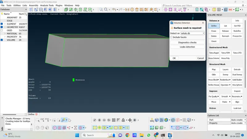
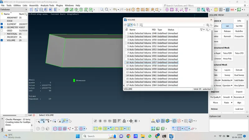
2. so hear 29 volume ansa detect in our geometry so we require wind tunnel volume which shown in follows. accept the wind tunnel volume and delete the remaining volumes.
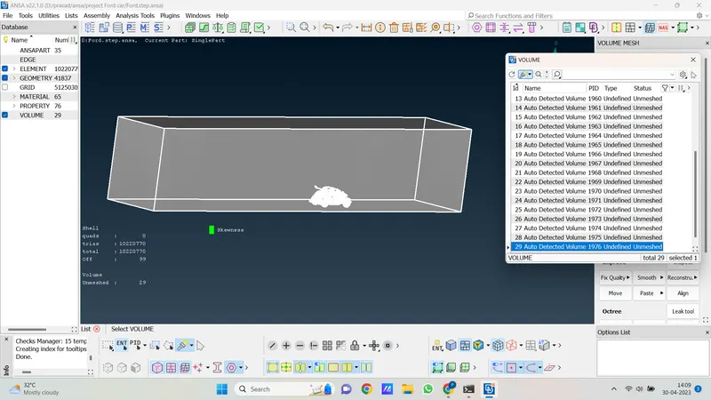
3. so the 29th no volume is tonne volume so we kept this volume and delete other volumes in the list.
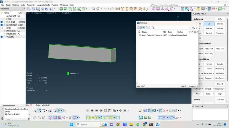
4. now write click on this volume and then click on remesh the volumetric mesh is started to creat.
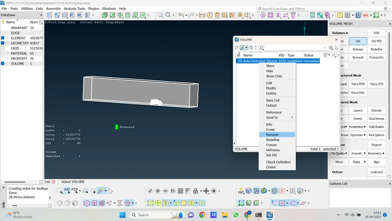
5. hear we do not perform volumetric because for volumetric meshing we require a strong system and my system is not suitable for that if I go to volumetric mesh my system is cracked and automatically ansa will close.
6. so hear our all steps on for car is done. we perform geometry cleanup, surface mesh, and volumetric mesh also create a wind tunnel and perform tyre crushing
Learning outcome:- In this project, we learn about ansa software we perform one project in this software and we again learn in this project about geometry cleanup, surface mesh, and volumetric mesh also we create a wind tunnel and performed tyre crushing. we go through all features of ansa exploring it.
Result:- geometry cleanup then surface meshing and volumetric meshing is done for the car model. and in total geometry we see 10220270 mesh elements are created in that 99 off elements are there and there is no unmeshed face remaining. the total geometry meshes successfully.
Conclusion:- gathering knowledge about ansa software and its different features also know deep knowledge of geometry cleanup, meshing, volumetric meshing, etc. and during volumetric mesh, we see for a volumetric mesh high-end system is required. and we don't have that much strong system so we can't able to go for volumetric mesh. also, we see when the target length is low it gets too much time for meshing geometry.
geometry link are shared below.
https://drive.google.com/file/d/1ZLkenlTDdprU3x0WkKzAuMPTdQolZhlH/view?usp=share_link