Wiring harness design in CATIA V5 - 3D modeling Week 5 & 6 Challenge
Aim. Route the following harness layout (Harness A & B) in the Electrical workbench.
1. Electrical Definition and Catalogue Creation
1.1. Define Connector
· Electrical Connector Part Number for Harness A: C-DT04-08PA-C017
C-1-174357-2
C-DT06-08SA-CE01
C-DT06-08SA-EP07
C-YDTS26F15-35SNV001
· Electrical Connector Part Number for Harness B: C-DT06-08SA
C-YDTS26F15-35SNV001
C-DT06-3S-CP01
C-DT06-08SA-CE04
C-DT06-08SA-EP07
C-DT06-08SA-CE13
Open Part to Electrical Part Design Workbench:
1. Switch Workbench to Part Design Workbench-
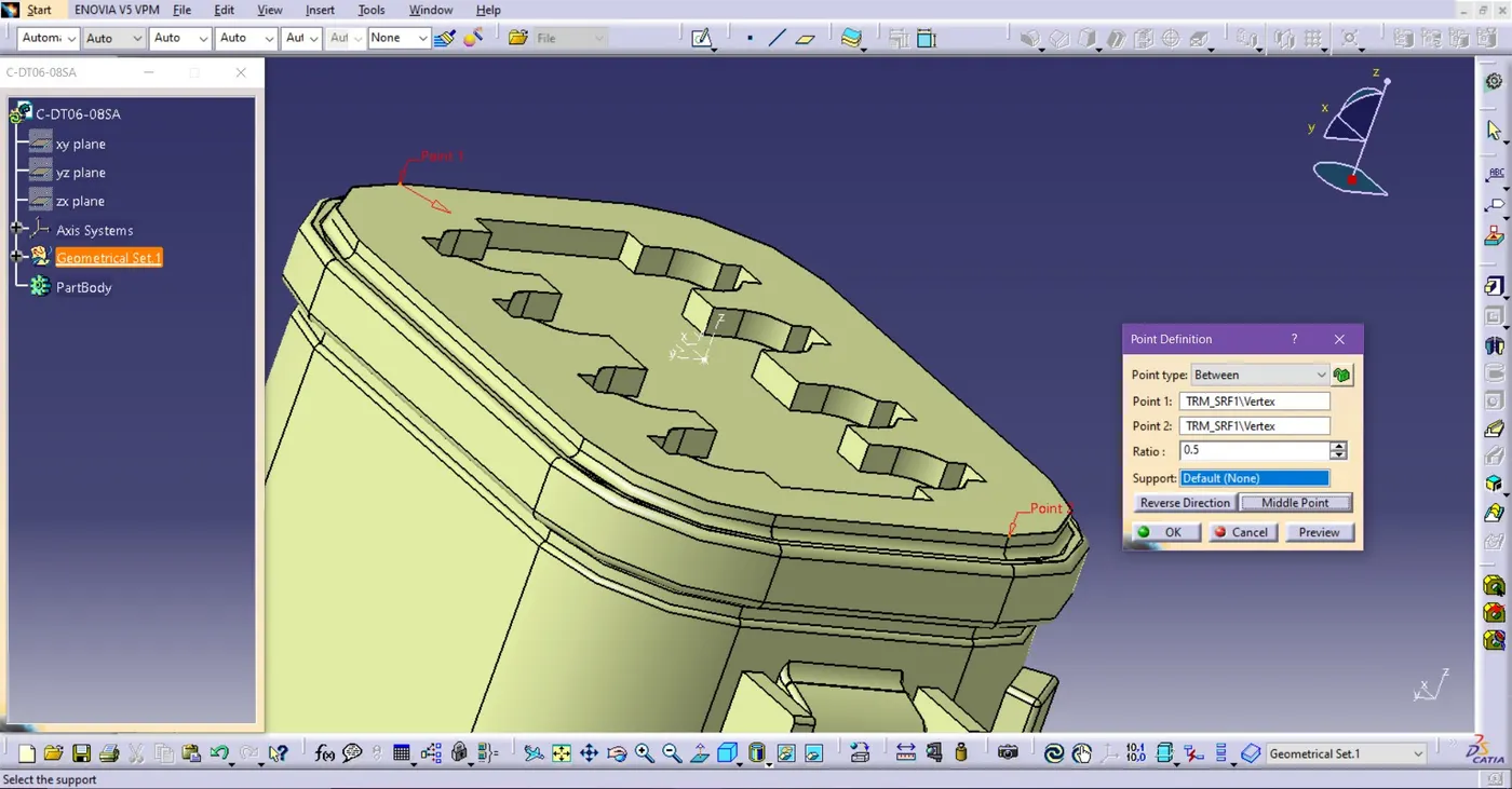
Fig. Make Point on the Connector Connection side
o Go to Point > Opened Point Definition > Choose Points and Set it to Middle point.
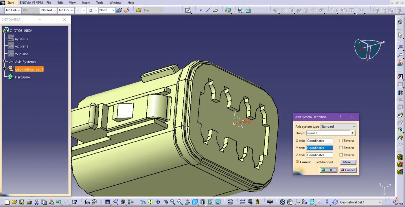
Fig. Axis System Definition of a Connector
o Set the Y-axis is on the direction of the connector’s connection
o Set the X-axis is on the direction of the Connector’s Lock side.
2. Switch Workbench to Electrical Part Design:
o Go to Start > Electrical Part Design to switch to the Electrical Part Design workbench.
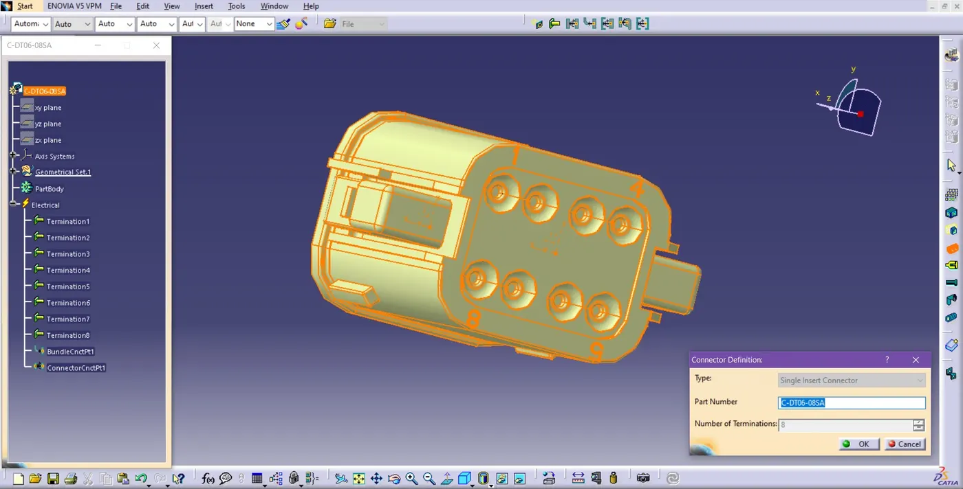
Fig. Connector Definition
o Define the connector with the ‘Define Connector’ Command and mention the number of the wire connections.
3. Define Electrical Properties:
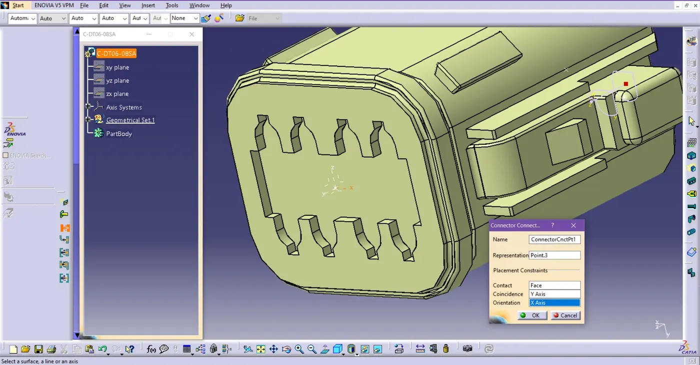
Fig. Define Connector’s Connection Point
o In the Electrical Part Design workbench, the ‘Define Connector Connection point’ command is to define the connector’s connection point, which is defined by ‘Axis system Definition’ at the front side of the connector.
o Go to the ‘Define Bundle Connection Point’ Command and choose the face of the connector side at the representation on the dialog box, click on the reference point, and again choose a face for the initial condition to define the bundle connection of the connector
The electrical part (Connectors) is now ready for the Electrical Harness Assembly (Harness A & B).
1.2. Prepare Catalogue
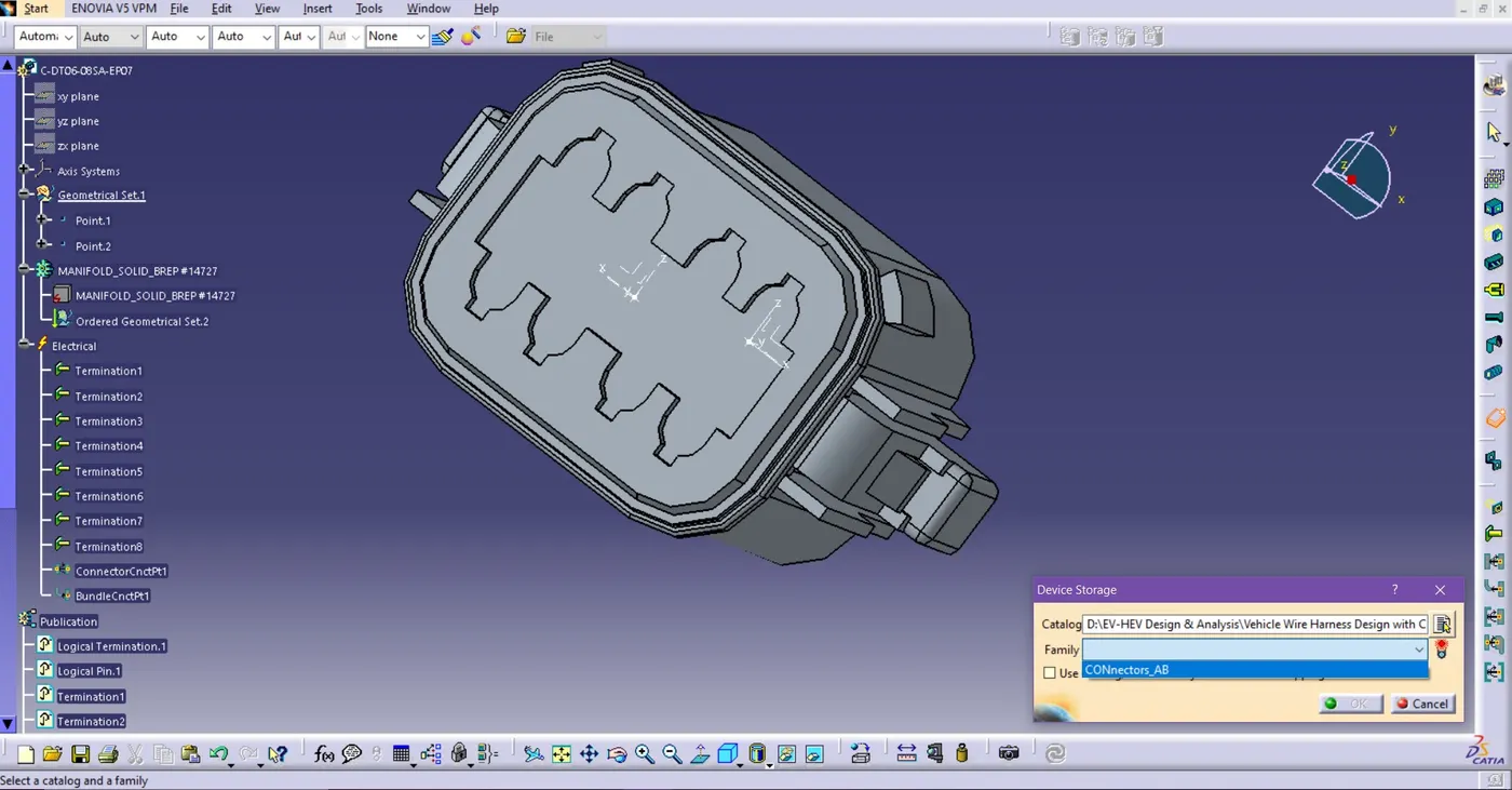
Fig. Add connectors in a Catalogue
o Create a new catalogue named ‘Connectors AB’ and add all connectors.
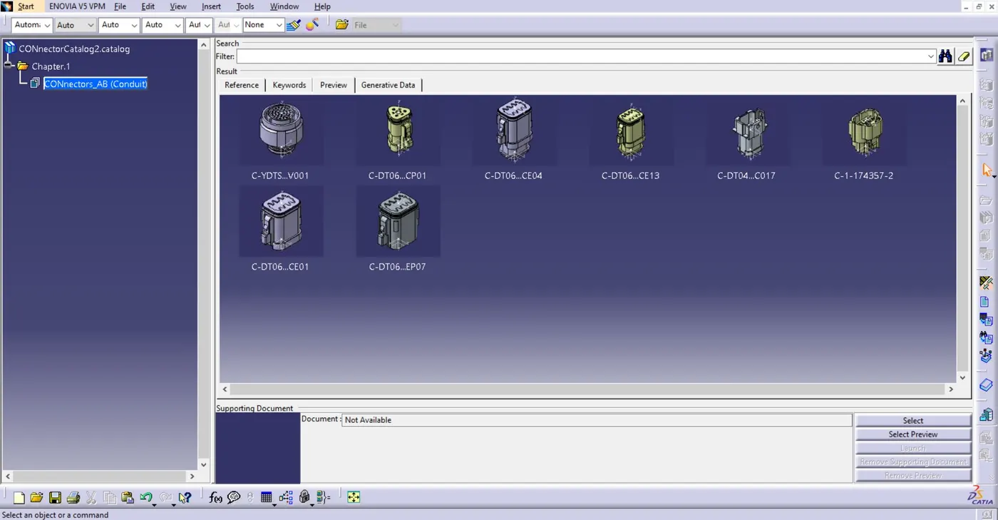
Fig. Catalogue ‘Connectors AB’
o To create this catalogue, open a new Catalogue window > Go to Add family > Choose type: Conduit.
o Add all connectors one by one to the catalogue.
2. Bundle Continuity and Annotation Creation
2.1. Bundle Continuity
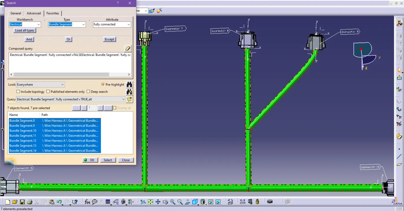
Fig. Bundle Continuity Check
o Go to Edit > Click Search, a window will pop up, Go to Advanced.
o Select ‘Electrical’ in Workbench
o Select ‘Bundle segment’ in Types.
o Select ‘Fully connected’ in Attributes.
o If you select ‘True’ then it will show connected bundle.
o If you select ‘False’ then it will show not connected bundle.
o That’s how you check bundle continuity.
2.2. Annotation Creation
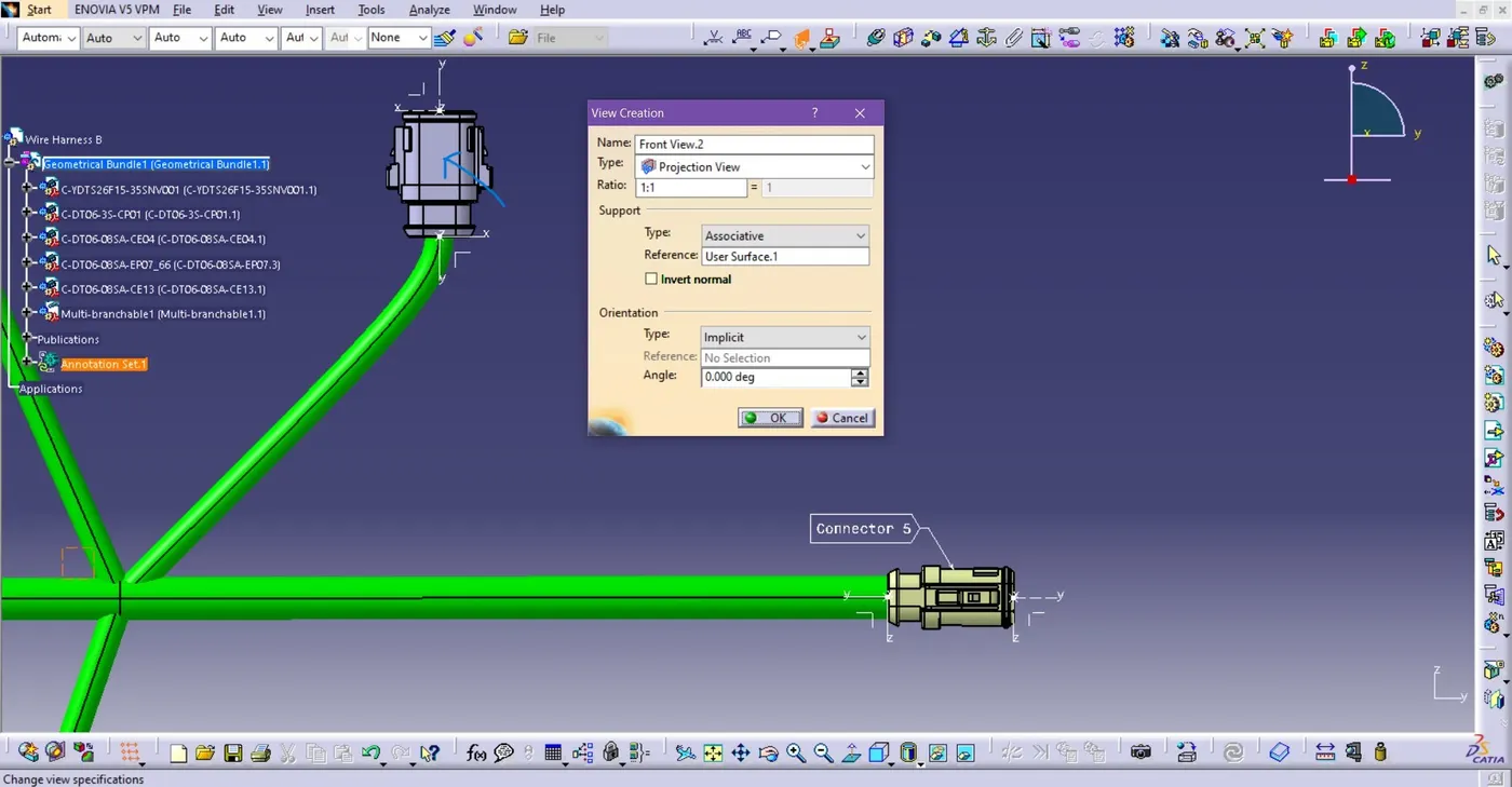
Fig. Define Plane for Annotations
o Go to view Creation, click it.
o Then pops up a window, click on surface for plane reference, then click Okay.
o Plane for Annotation is created.
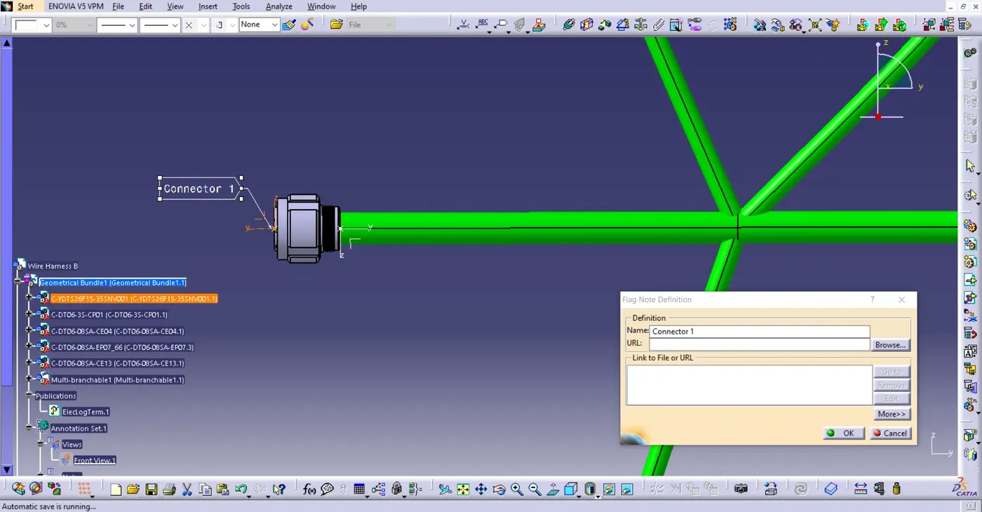
Fig. Flag Note definition
o Click to Flag note Definition, then click to connector.
o Give annotations to all connectors.
3. Preparation for Interconnection
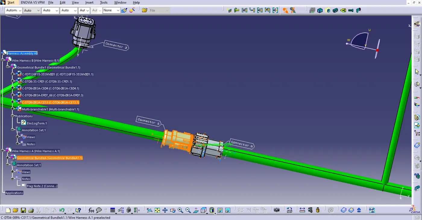
Fig. Connector Connection
o Add both the Harness A and B in a single product tree
o Change the workbench to Electrical Assembly Design
o Click ‘Connector Connection’ option then select both the connectors.
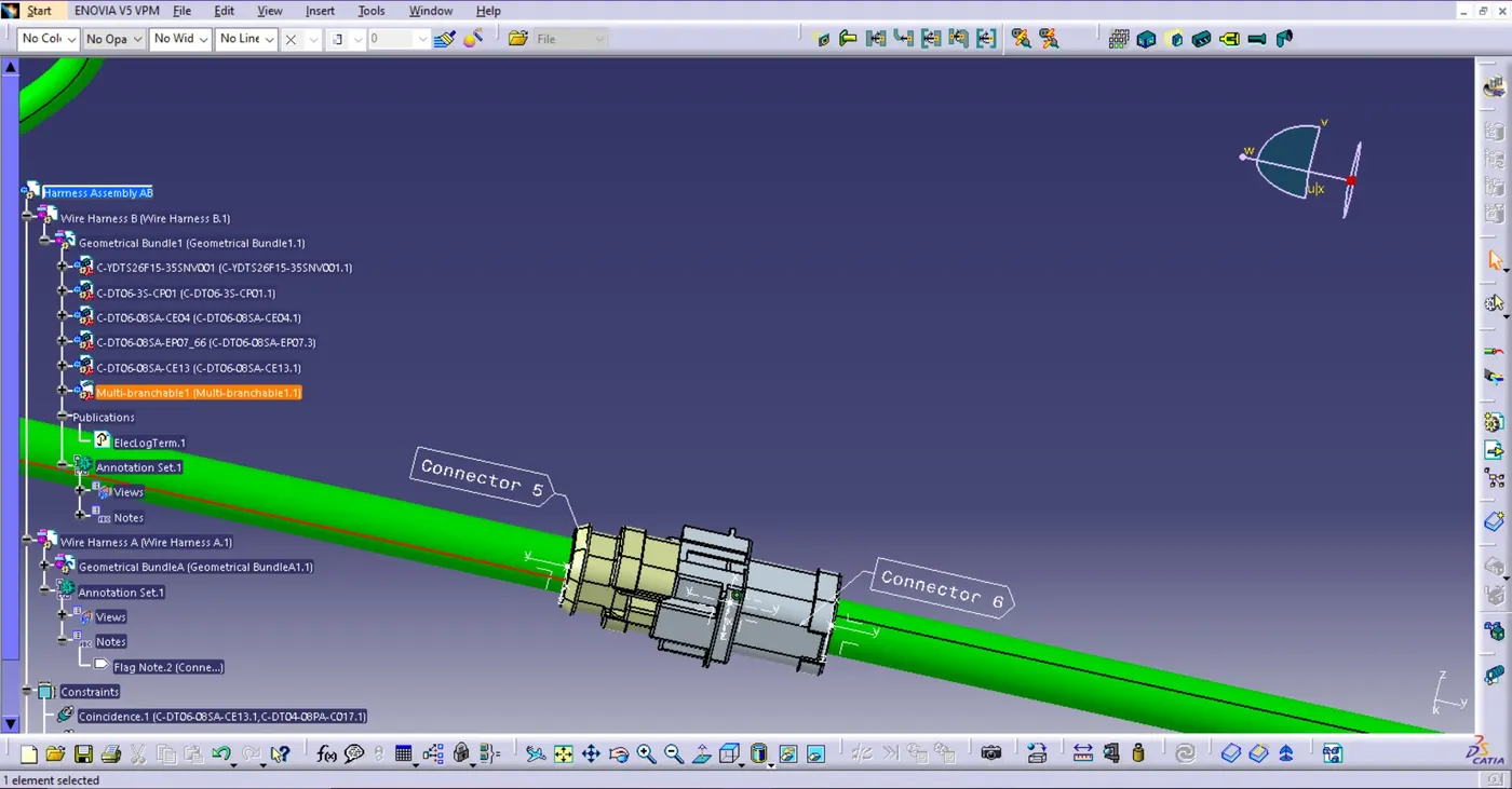
Fig. Connected Connector
1. Prepare working file
After cross-checking the whole task, all the bundles are connected and connectors are fully defined.
There is no bundle warning shown after completion.
o Now Generate the .CATpart from product.
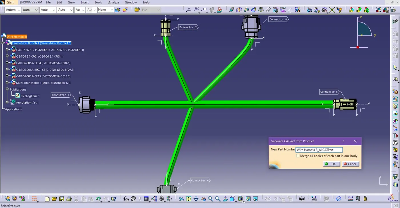
Fig. Generate CATpart
o Change the workbench into ‘Assembly Design’.
o Go to Tools > Click Generate CATpart from product.
o
Wait for some time to generate CATpart.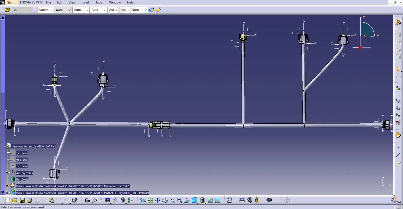
Fig. Generated CATpart of Interconnected Assemebly
o After generation of CATpart, all the colors and annotations are removed.
o We have to annotate and colour again in CATpart.
Working files Are attached below.