Wiring harness routing & packaging Rules Week 3 Challenge
Q1. Define a P Clamp as Electrical Support using an Electrical part design workbench.
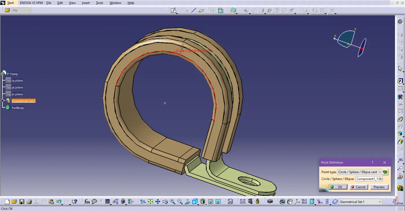
Fig. Define Point
1.1 Open the P-Clamp CAD File
o Open the P-Clamp CAD file in CATIA and switch the workbench to Part design.
o Define point of the P Clamp
1.2. Define Entry/Exit base Planes in P Clamp.
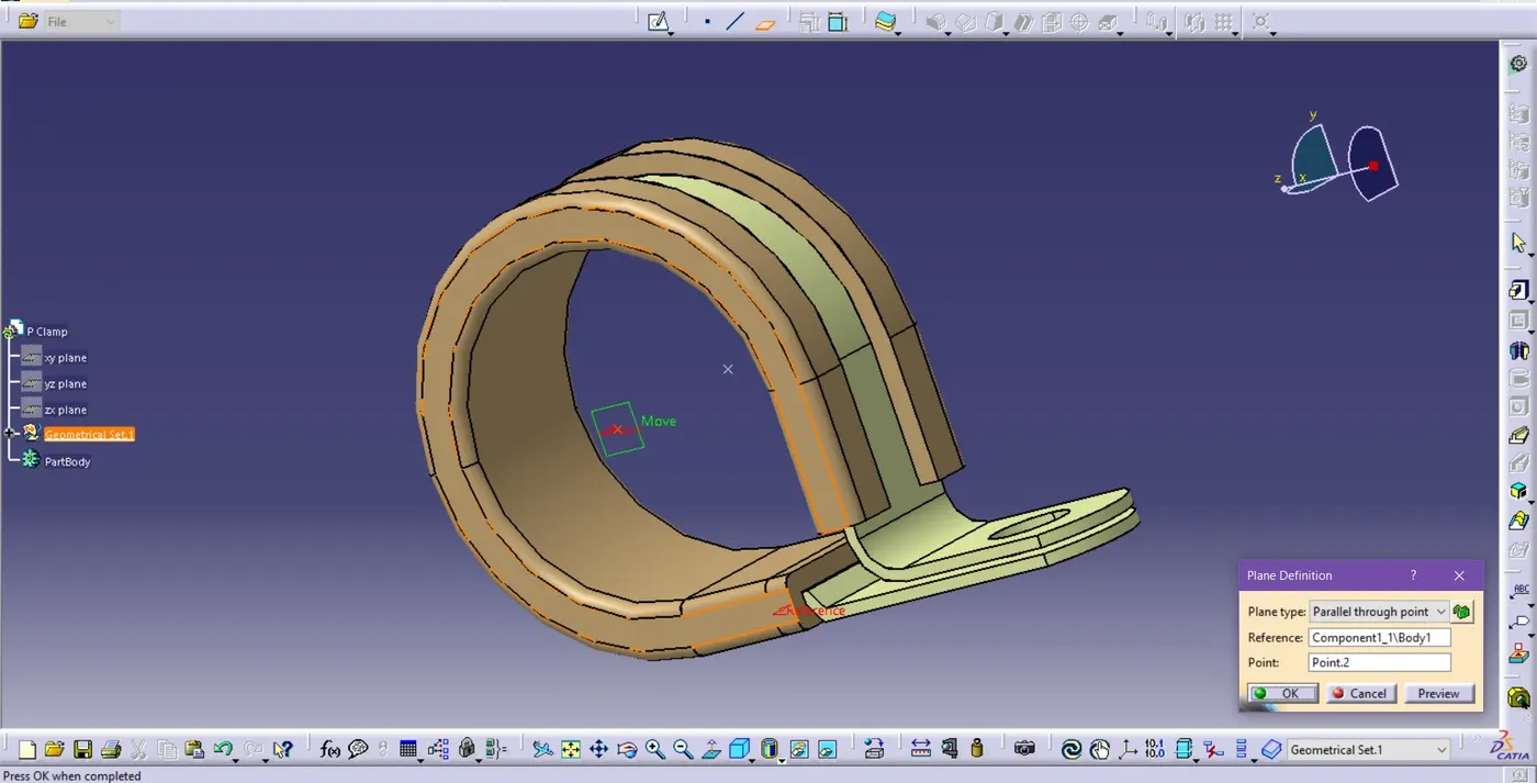
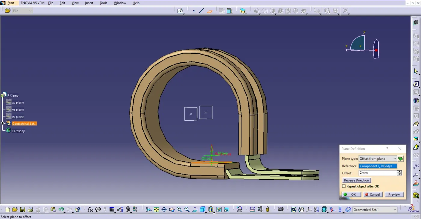
Fig, Define Entry/Exit & Base Plane
o Define plane for entry point > select entry point, exit point, and then Base plane which is 2mm offset from the surface.
1.3. Switch to Electrical Part Design Workbench
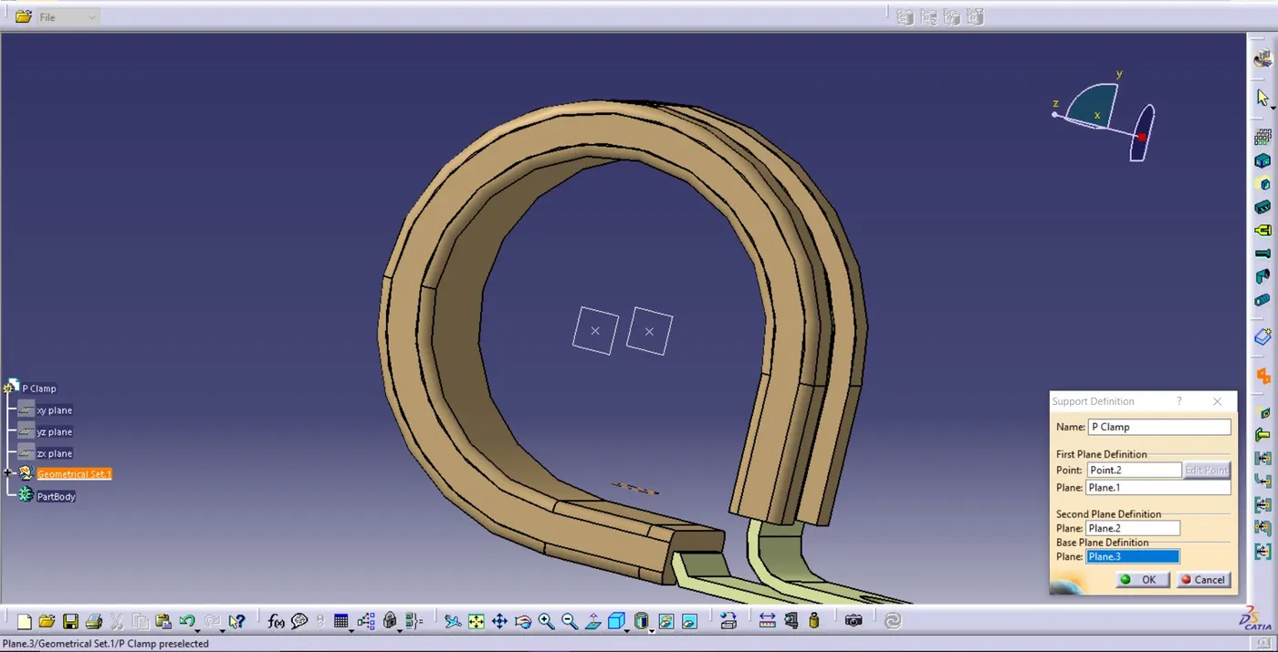
Fig. Plane Definition
o Define support for entry point > select point then select entry plane, exit plane, and then Base plane.
o
Same Repeat the process but this time from
the opposite direction because now we define a support exit point.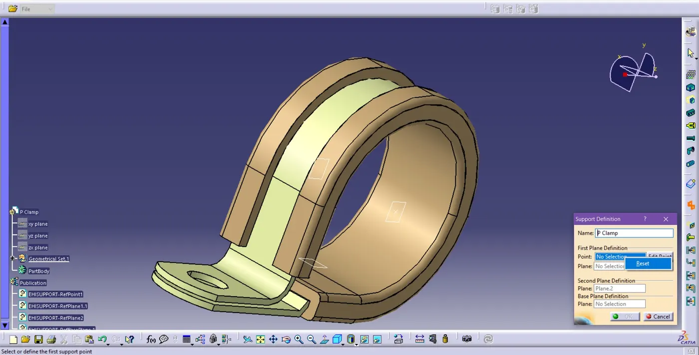
Fig. Reset point selection for exit
o While selecting the point for the exit of P Clamp in support definition, need to reset the point by right-clicking> Reset, then we can select the exit point and plane and base plane, the entry point will be already defined.
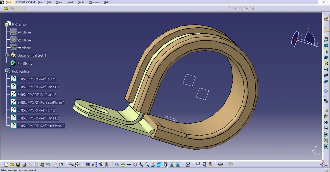
Fig. Fully defined entry/Exit point of P Clamp as Support Device
o This Electrical Part is ready to use.
o We can check in the publication also, it is fully defined.
Q2. Back shell cad data & define it as an Electrical back shell using an Electrical Part design Workbench. Define all the necessary properties.
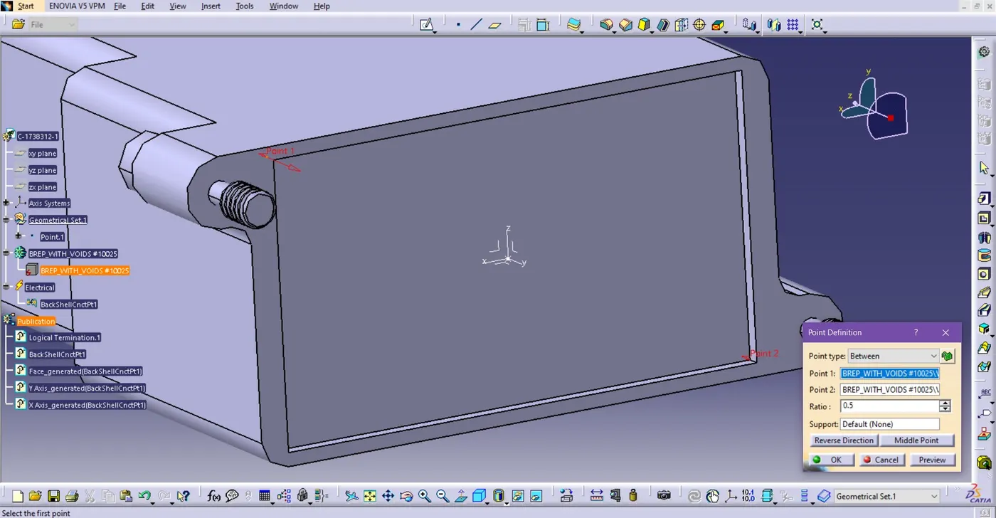
Fig. Point Definition
i. Define the point at the place of the connector connection point of the Back Shell.
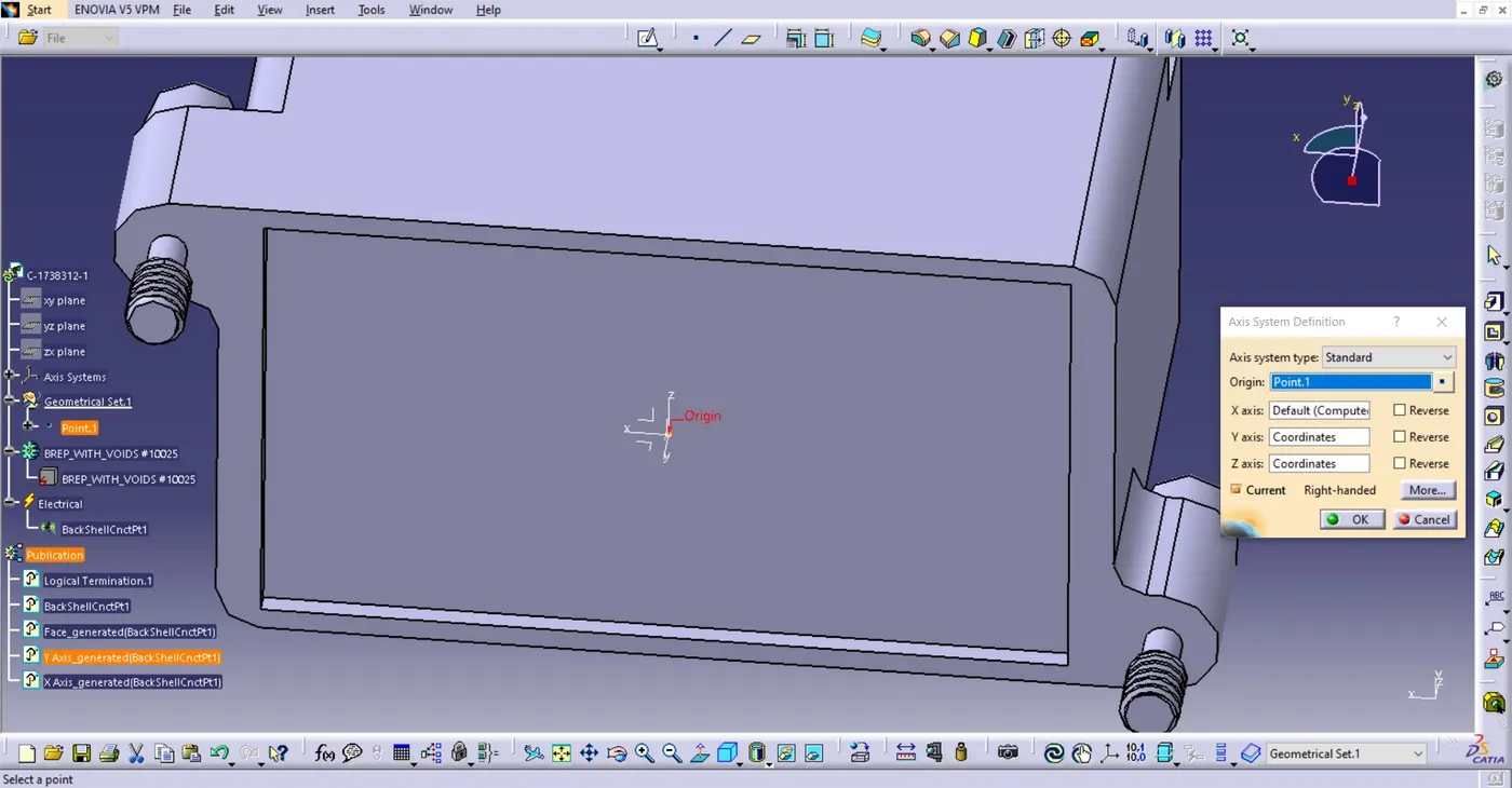
Fig. Axis System Definition
i. Define the axis system of the Back Shell the same as a connector, y-axis at the connection direction the x-axis at the locking direction.
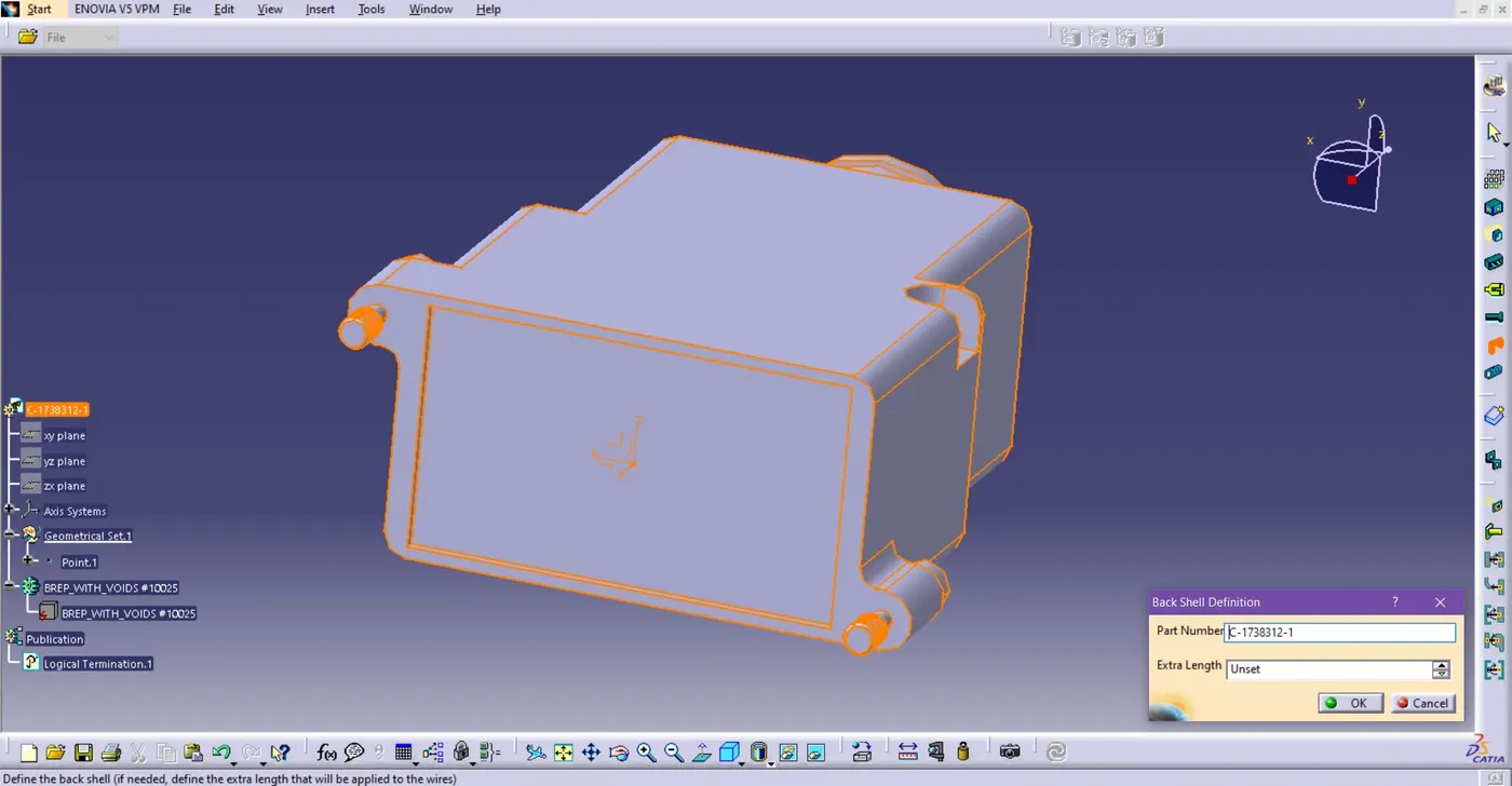
Fig. Back Shell Definition
i. Change workbench to Electrical Part design
ii. Go to Define Back Shell > select the part and define the part by clicking OK.
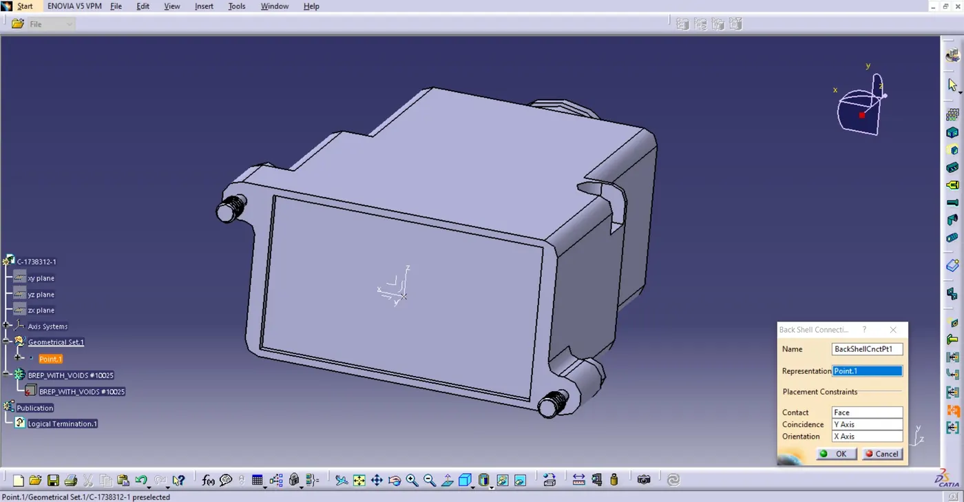
Fig. Define connection point
i. Define Back Shell Connector point, the reference point will be the representation, contact will be the face, connection direction(coincidence) will be the y-axis, and the orientation will be x-axis.
ii. Now the part is ready.
Q3. Create Following Corrugated tubes & Add them in Catalogue under “Slit COT” family.
|
Name |
ID (mm) |
OD (mm) |
Thickness (mm) |
|
15mm COT |
12 |
15 |
1.5 |
|
20mm COT |
17 |
20 |
1.5 |
|
35mm COT |
32 |
35 |
1.5 |
|
10mm COT |
7 |
10 |
1.5 |
|
5mm COT |
3 |
5 |
1 |
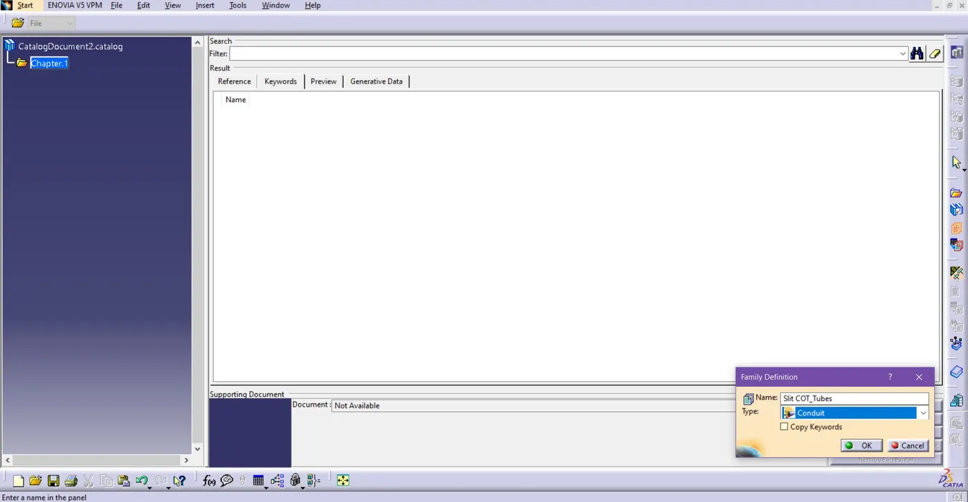
Fig. Define Family of Slit COT Tube in Catalogue
· Create as new Catalogue, Go to New > Select Catalogue, then file will be open then, Add Family > rename it ‘Slit COT Tubes’ and select type ‘Conduit’.
· Now we can make Corrugated tubes and add them in the Catalogue.
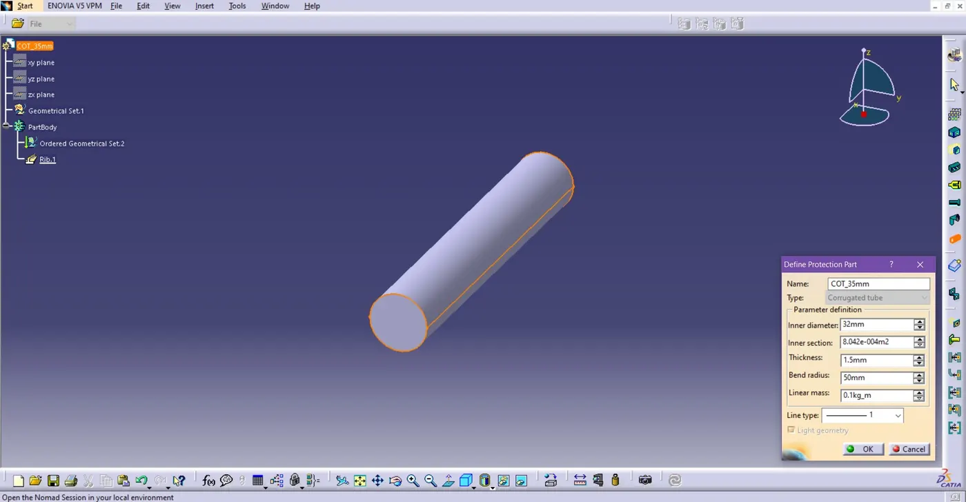
Fig. Define Protection part of COT 35mm tube
· To define the protective part, Change workbench to Electrical part design.
· Go to define protection part > select part body on the tree > opens dialog box to edit inputs according to the requirements.
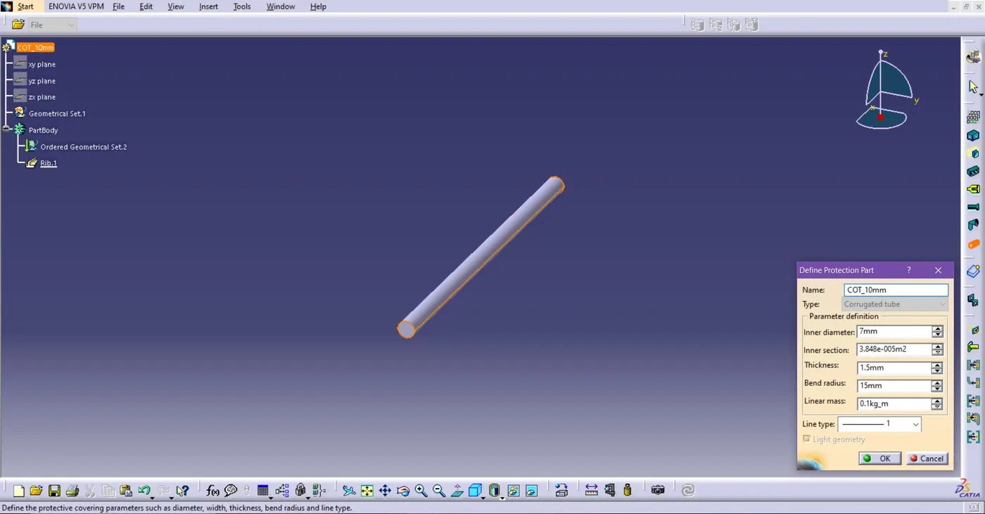
Fig. COT 15mm Defined as a protection part
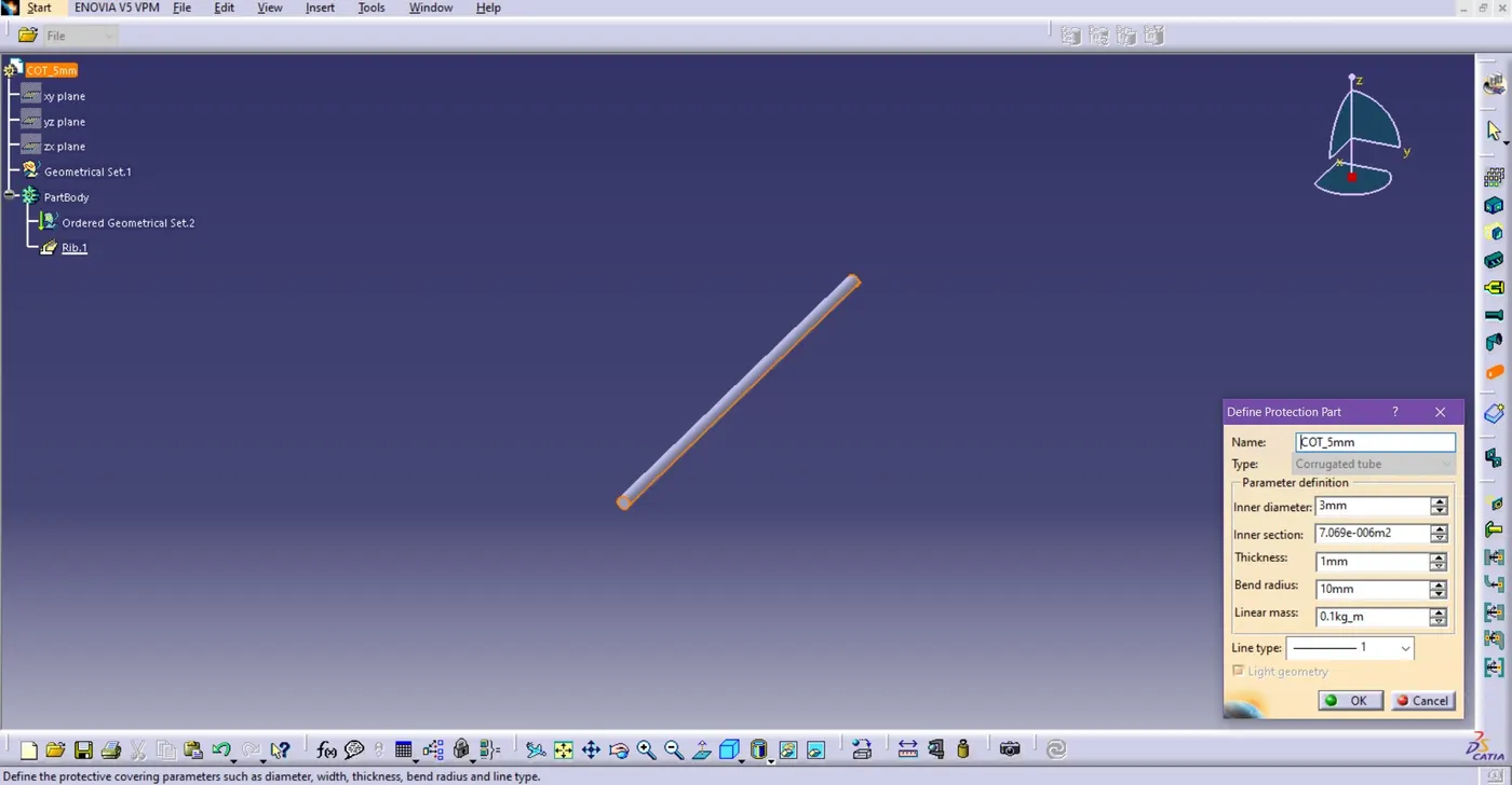
Fig. COT 5mm Defined as a protection part
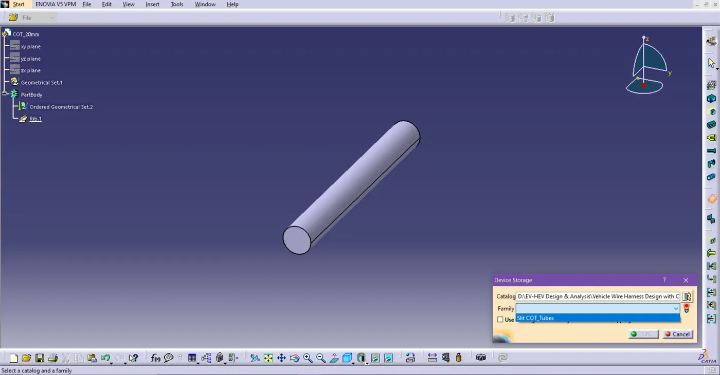
Fig. Add COT 20mm to Catalogue
· After creating COT tubes, add it to the ‘Slit COT tubes’ criteria in the Catalogue which we made before.
· Now click to catalogue > Select ‘Slit COT tubes’ in a family section and click OK.
· All these Corrugated tubes are added separately in the ‘Slit COT Tubes’ section in a catalogue