Wiring harness design in CATIA V5 - 3D modeling Week 4 Challenge
Electrical Harness Routing and Documentation in CATIA V5
1. Introduction
This report details routing an electrical harness layout using the Electrical Workbench in CATIA V5. The layout consists of multiple connectors, wiring branches, and protective coverings as per the given schematic. The project also involves defining the bundle diameters and adding protective coverings to designated branches.
2. Objective
- Route the electrical harness as per the given layout.
- Define appropriate bundle diameters based on assumptions.
- Ensure the use of protective coverings for specified connectors.
- Maintain an end extremity of 30mm from the connector end for protective coverings.
- Generate a detailed CATIA V5 model of the harness layout.
3. Components Used: The following connectors were downloaded from www.te.com and used in the project:
- DT06-4S
- DT06-6S
- DT06-2S
- DT06-08SA
4. Procedure:
Electrical Connector Part Number: C-DT06-08SA
Open Part to Electrical Part Design Workbench:
1. Switch Workbench to Part Design Workbench-
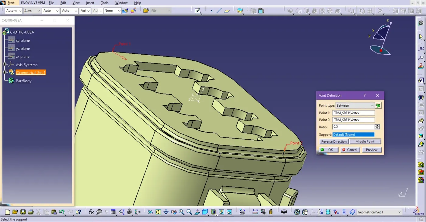
Fig. Make Point on the Connector Connection side
o Go to Point > Opened Point Definition > Choose Points and Set it to Middle point.
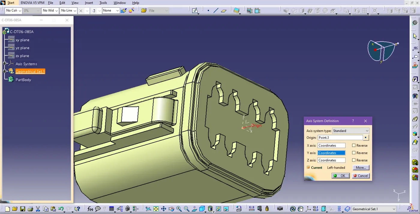
Fig. Axis System Definition of a Connector
o Set the Y-axis is on the direction of the connector’s connection
o Set the X-axis is on the direction of the Connector’s Lock side.
2. Switch Workbench to Electrical Part Design:
o Go to Start > Electrical Part Design to switch to the Electrical Part Design workbench.
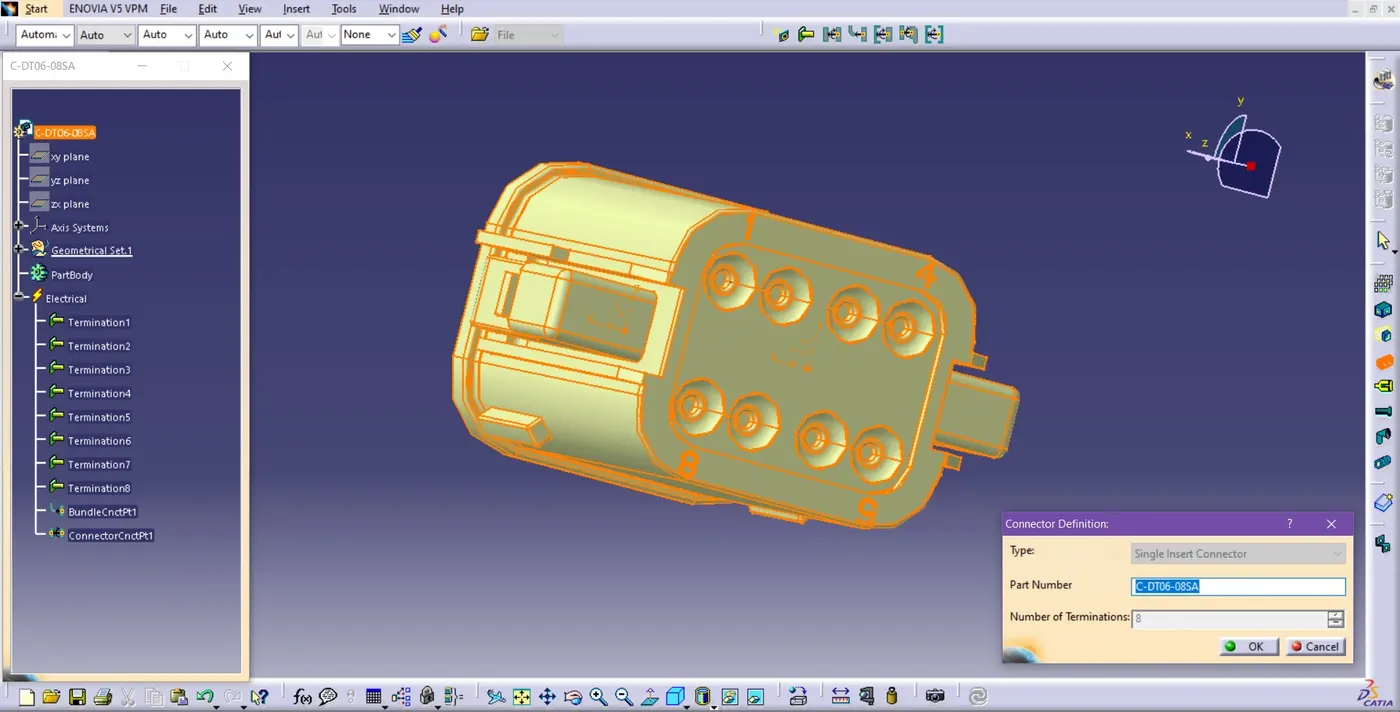
Fig. Connector Definition
o Define the connector with the ‘Define Connector’ Command and Mention the number of the wire connections.
3. Define Electrical Properties:
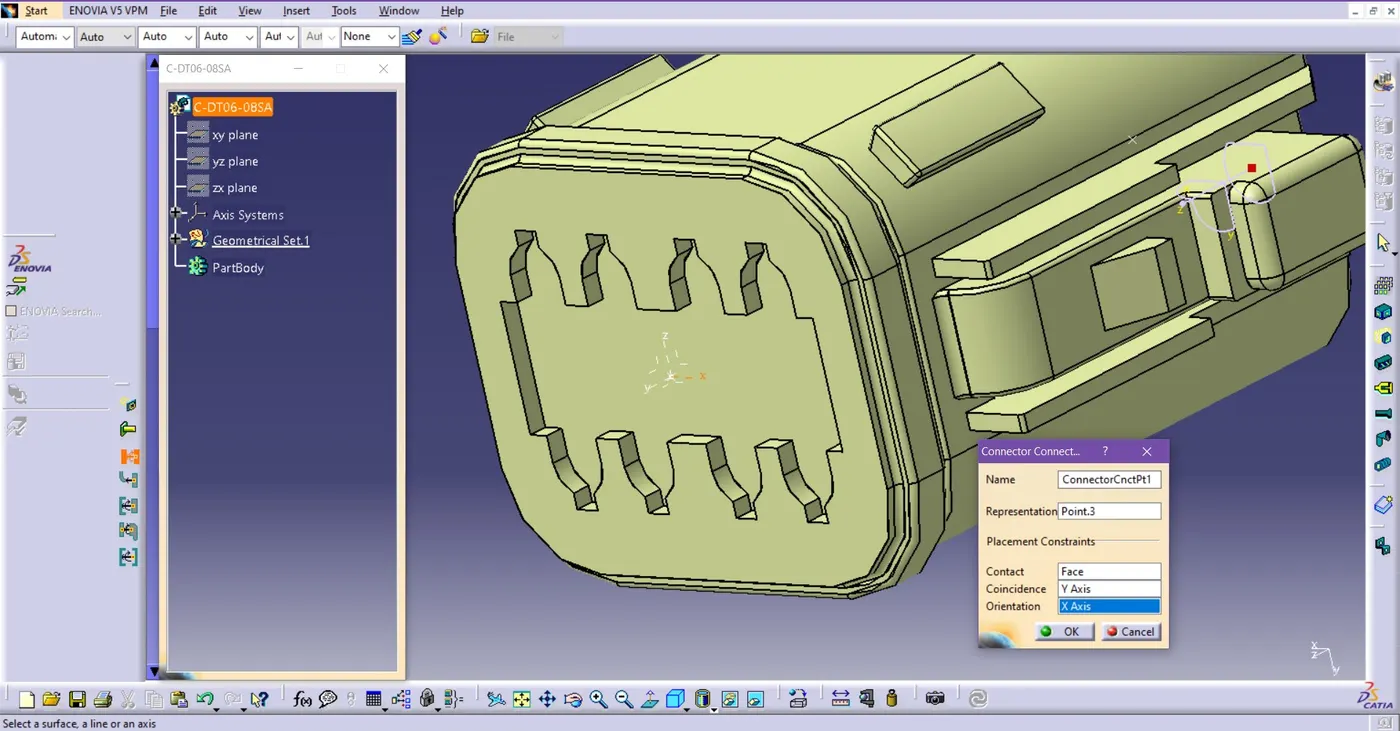
Fig. Define Connector’s Connection Point
o In the Electrical Part Design workbench, the ‘Define Connector Connection point’ command is to define the connector’s connection point which is defined by ‘Axis system Definition’ at the front side of the connector.
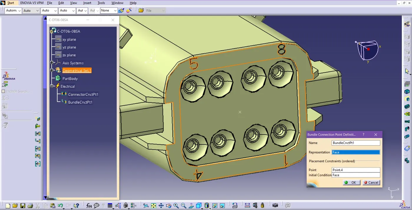
Fig. Bundle Connection Point Definition
o Go to the ‘Define Bundle Connection Point’ Command and Choose the face of the connector side at the representation on the dialog box, Click on the reference point and again choose a face for the initial condition to define the bundle connection of the connector
The electrical part (Connector) is now ready for the Electrical Harness Assembly and do this with all the necessary connectors that are used.
4. Switch to Part design Workbench-
o Import all the Connectors.
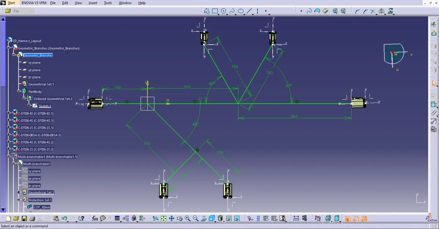
Fig. 4.1. Harness Routing Geometrical Set-up
o Arrange all the connectors According to the given routing geometrical Setup.
5. Switch to Electrical Harness Assembly workbench-
o Go to the Geometrical Bundle option then, Click on Product tree.
o After Clicking the main product tree, there will be a ‘Multi-Branchable’ as a Sub-Product added to the tree.
o Ensured all connectors were properly positioned and linked using the electrical bundle tool.
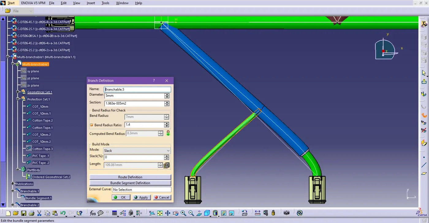
Fig.4.2. Branch Definition of Connector (C-DT06-4S) 5mm Left
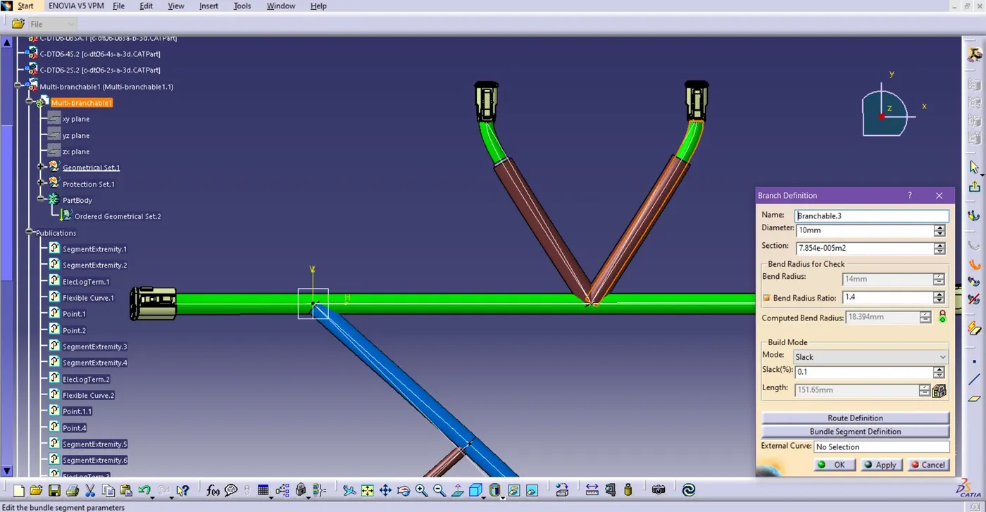
Fig. 4.3. Branch Definition of connector (C-DT06-2S) 10mm
o These branches of connectors ‘C-DT06-2S’ are 10mm in diameter and according to schematics, the length of both branches is 150mm.
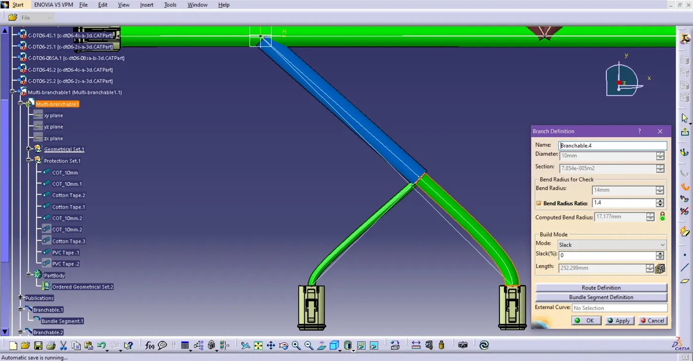
Fig.4.4. Branch Definition of Connector (C-DT06-4S) 10mm at Right.
o 0.1 % slack for all the 10mm and 5 mm branches to adjust the wire curves.
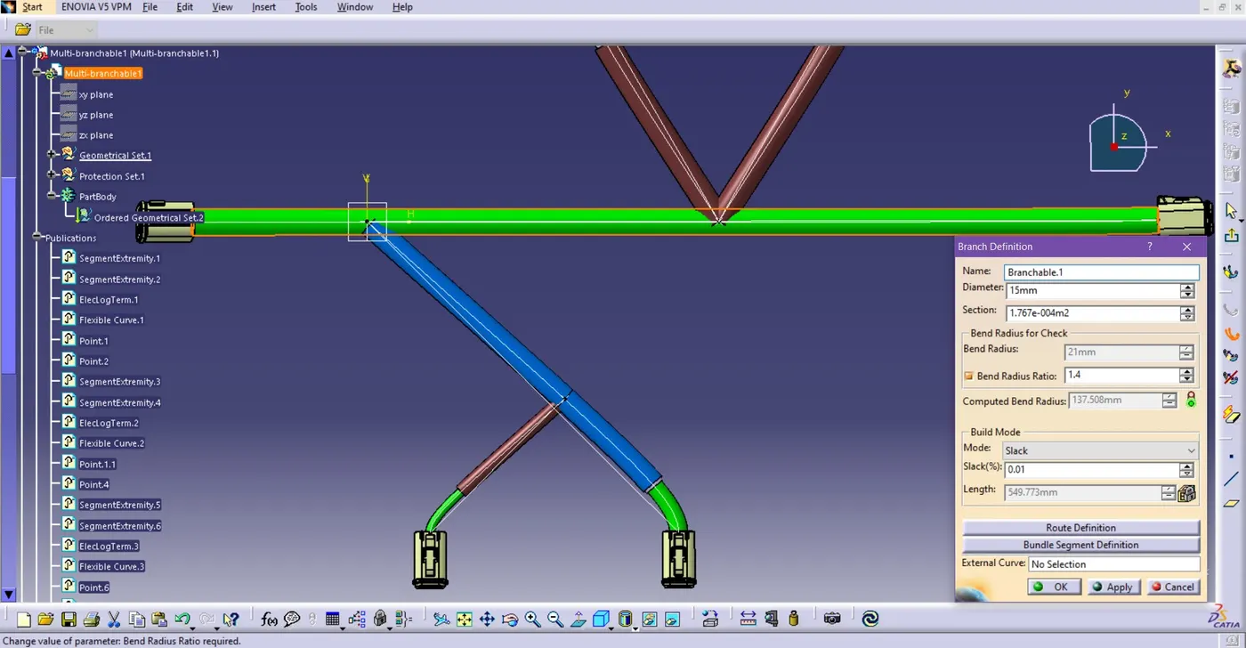
Fig.4.5. Branch definition of main connections (15mm)
o 0.01% slack to eliminate minor errors in the connection.
6. After completion of wire harness routing, we now begin with Light protection coverings on harness routing, such as Corrugated tubes, PVC tape, and Cotton tape.
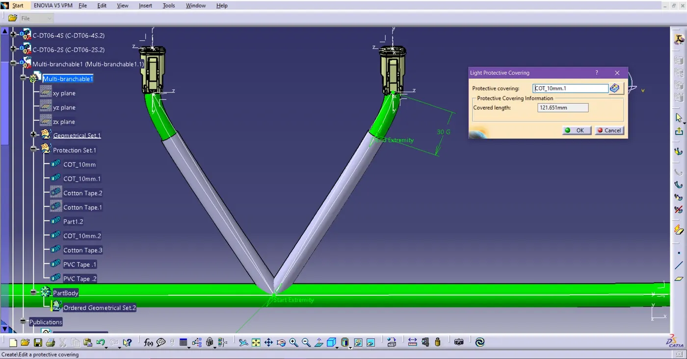
Fig. 4.6. Protecting Covering on 10mm Diameter wire
o Put the protection covering on the wire connection and leave 30mm of end extremity point for these connectors connection, DT06-4S and DT06-2S.
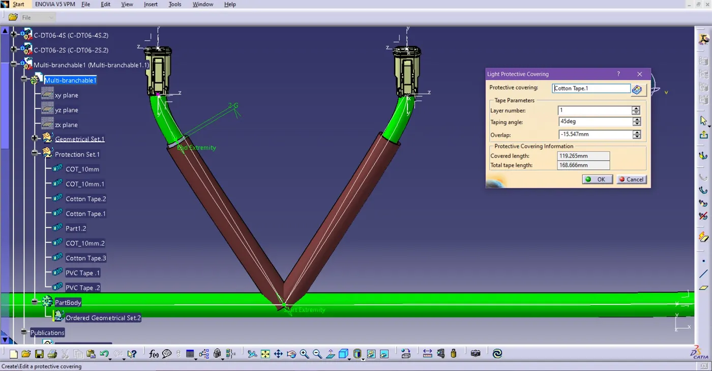
Fig. 4.7. Cotton Tape as Light protection covering on 10mm wire
o I have left 2mm extra extremity points for two different representations of protection covering COT tube and cotton tape.
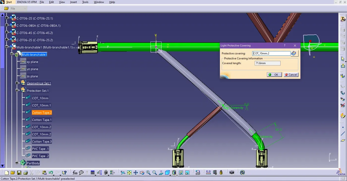
Fig. 4.8. Corrugated tube as protection covering with 30mm of end Extremity
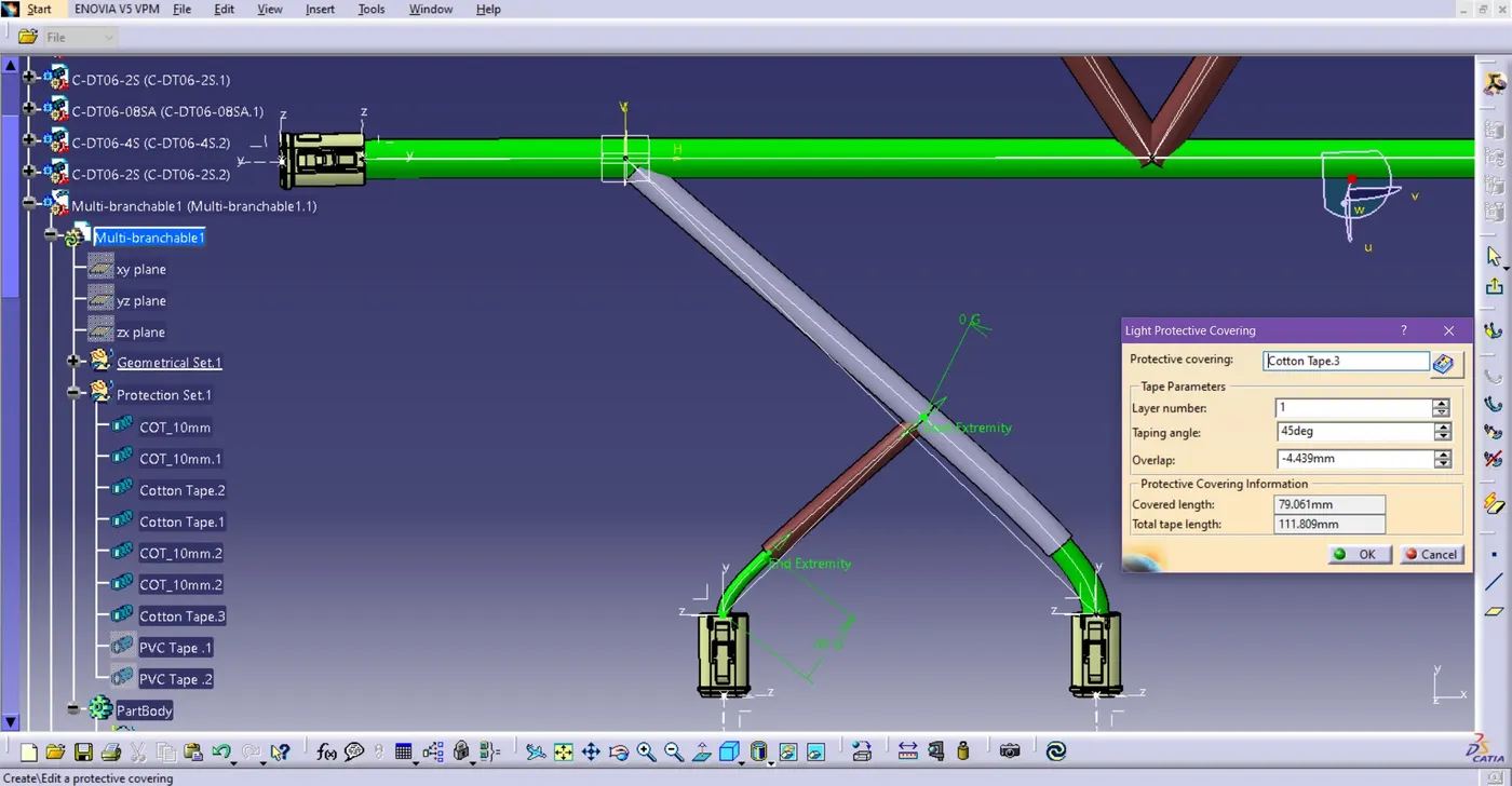
Fig. 4.9. Cotton tape as protection covering with 30mm end extremity
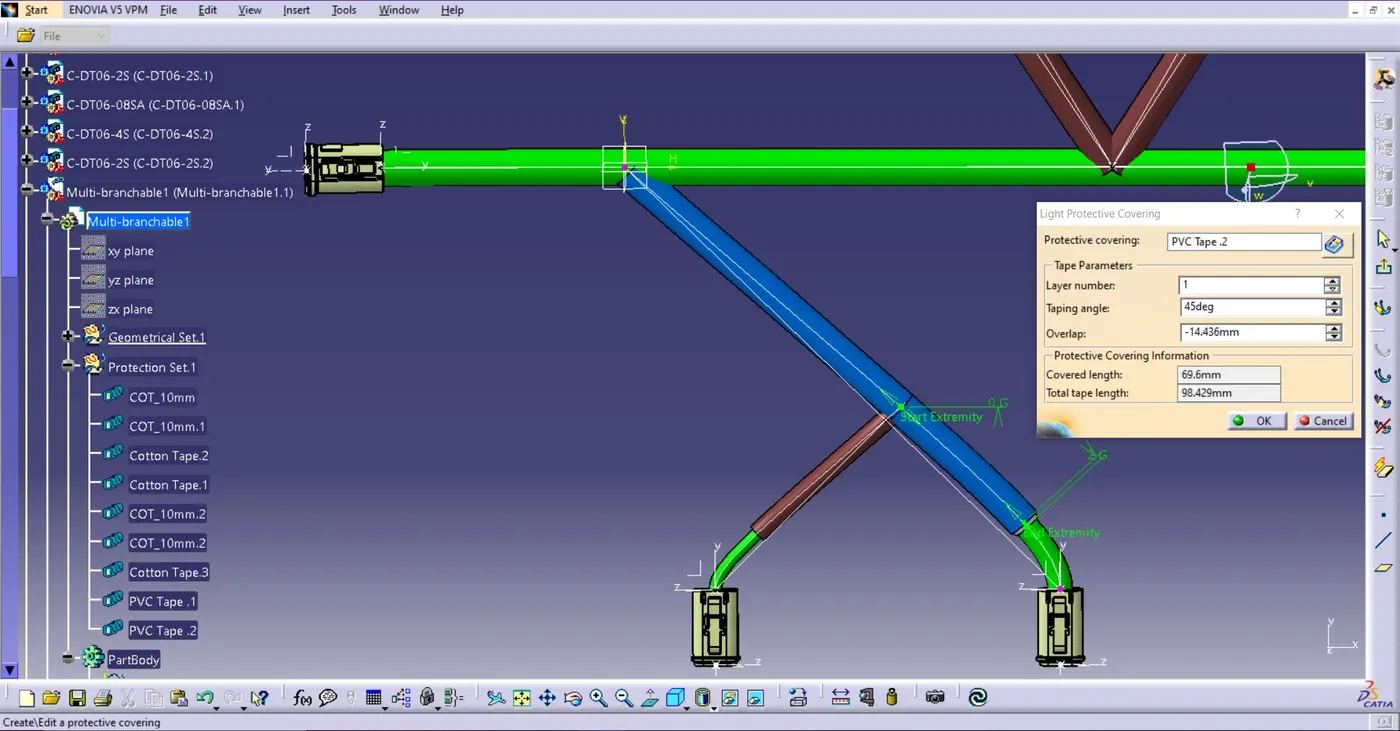
Fig. 4.10. PVC Tape as protection covering at connector connection (DT06-4S)
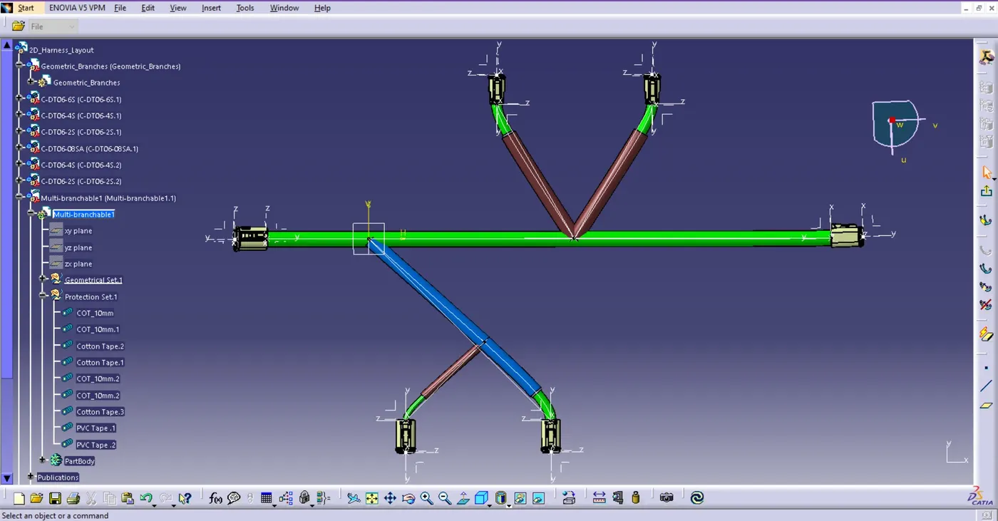
Fig. 4.9. Overview of Wiring Harness Assembly