Wiring harness design in CATIA V5 - 3D modeling Week 2 Challenge
Define connectors & Connector clips as Electrical connectors using the Electrical Part Design Workbench. (Catia V5)
Electrical Connector Part Number: C-DT06-08SA
Open Part to Electrical Part Design Workbench:
1. Switch Workbench to Part Design Workbench-
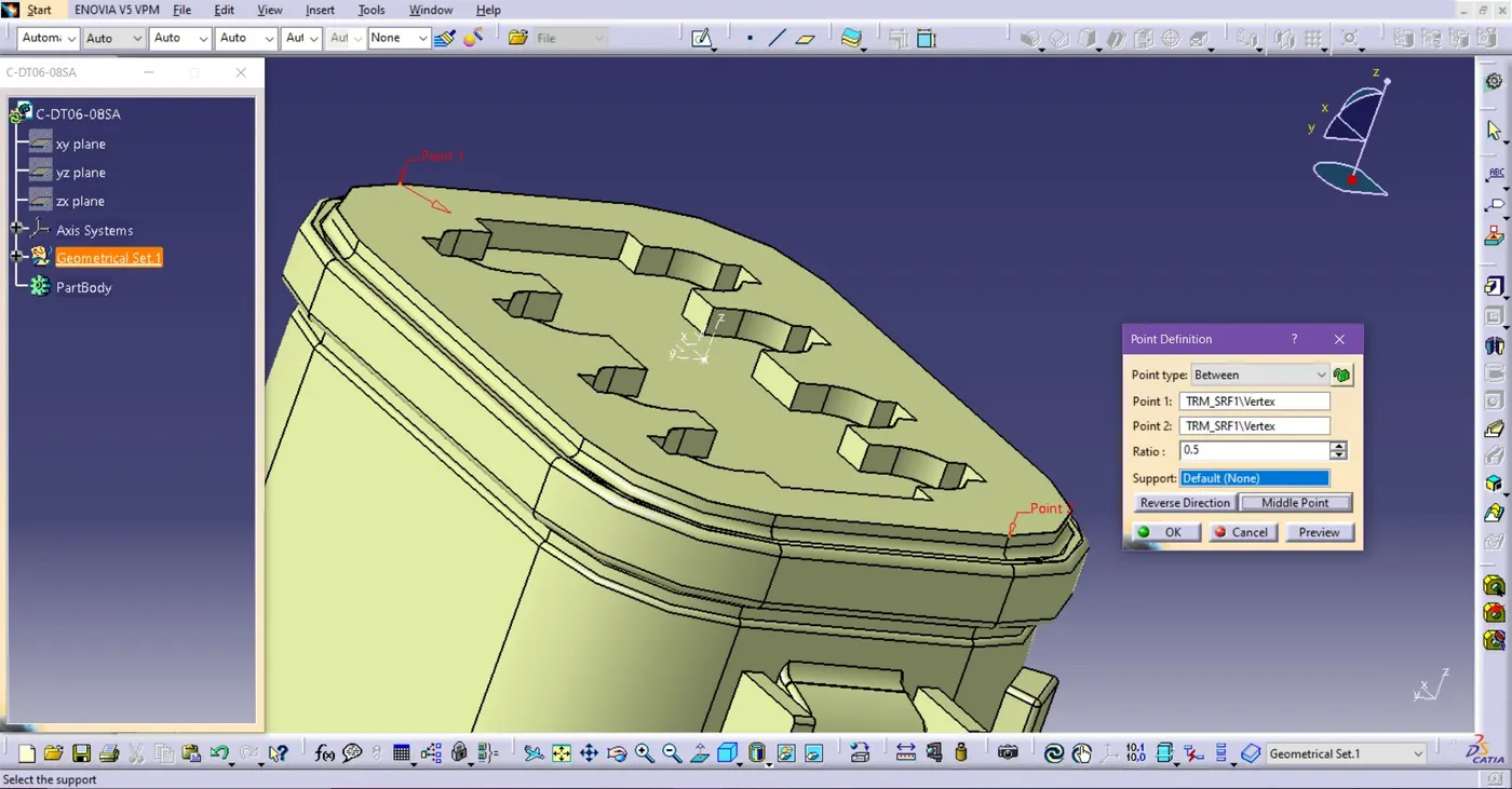
Fig. Make Point on the Connector Connection side
o Go to Point > Opened Point Definition > Choose Points and Set it to Middle point.
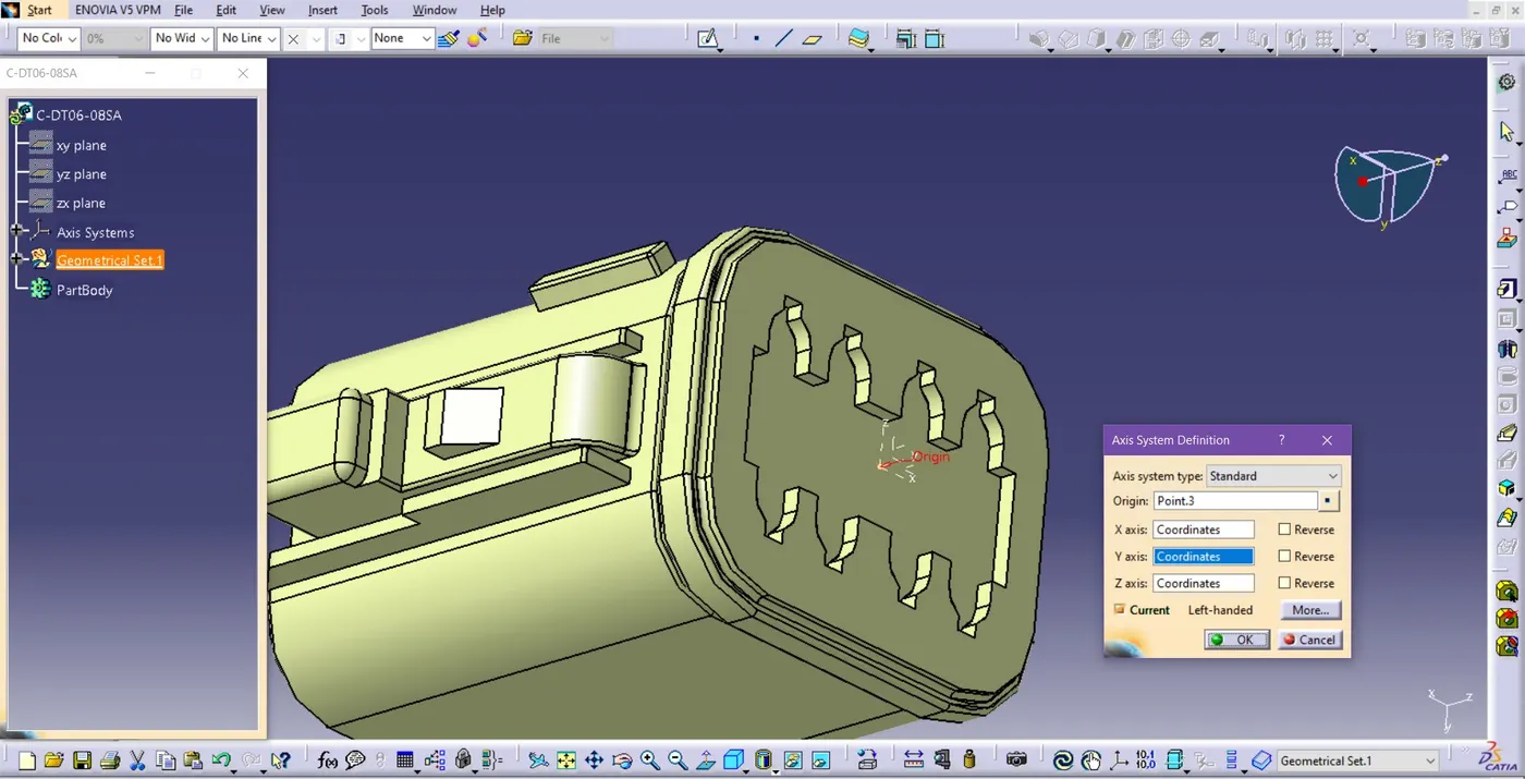
Fig. Axis System Definition of a Connector
o Set the Y-axis is on the direction of the connector’s connection
o Set the X-axis is on the direction of the Connector’s Lock side.
2. Switch Workbench to Electrical Part Design:
o
Go to Start > Electrical
Part Design to switch to the Electrical Part Design workbench.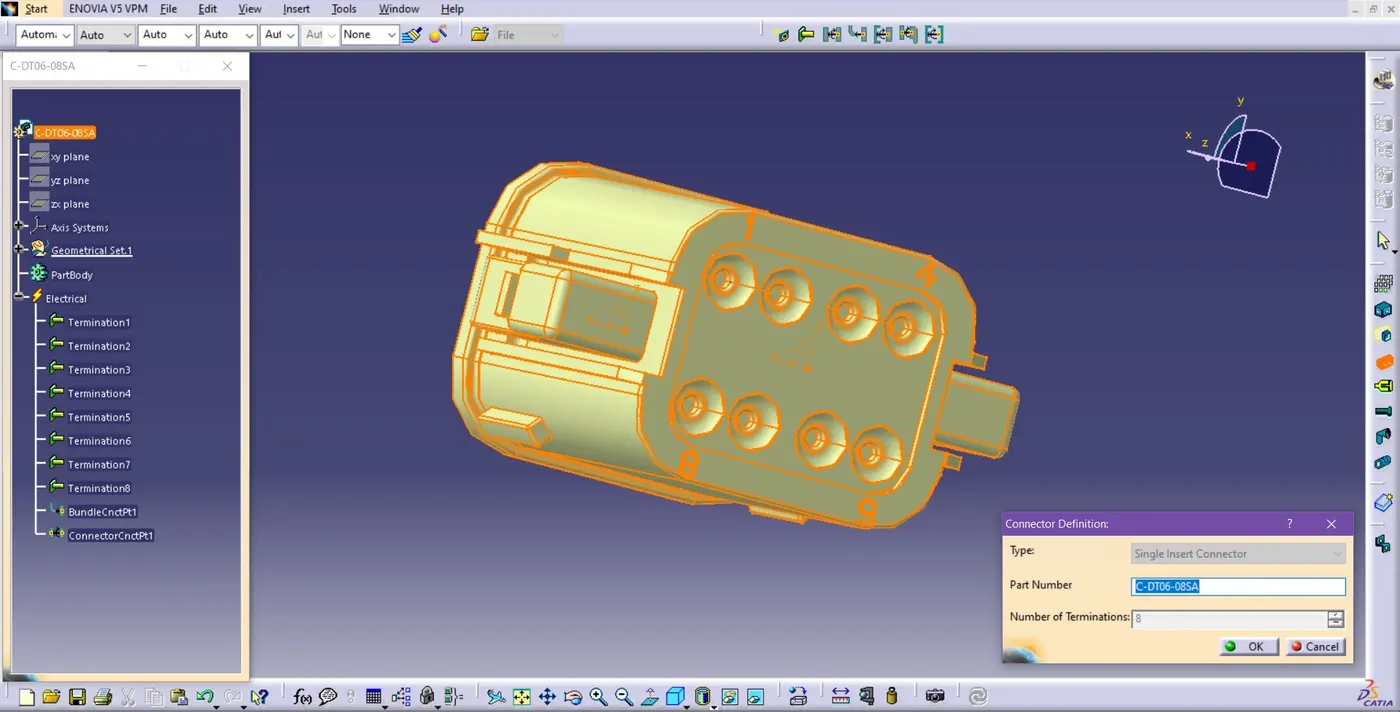
Fig. Connector Definition
o Define the connector with the ‘Define Connector’ Command and Mention the number of the wire connections.
3. Define Electrical Properties:
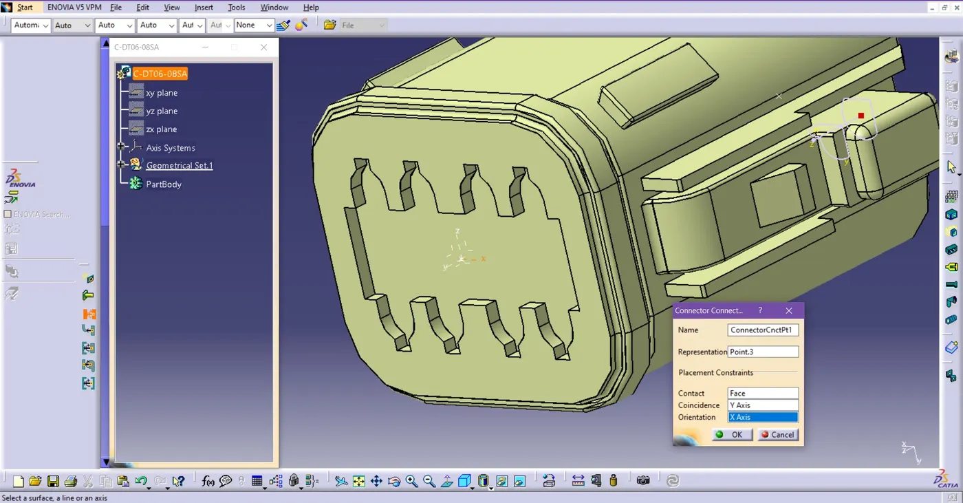
Fig. Define Connector’s Connection Point
o In the Electrical Part Design workbench, the ‘Define Connector Connection point’ command defines the connector’s connection point defined by ‘Axis system Definition’ at the front side of the connector.
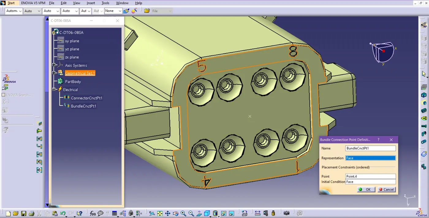
Fig. Bundle Connection Point Definition
o Go to the ‘Define Bundle Connection Point’ Command and Choose the face of the connector side at the representation on the dialog box, Click on the reference point and again choose a face for the initial condition to define the bundle connection of the connector
The electrical part (Connector) is now ready for the Electrical Harness Assembly.
Ø Connector and Connector Clip Assembly in Electrical Assembly Workbench.
o Electrical Connector Part Number: C-2-174357-2.
o Electrical Connector Clip Part Number: C-0085229-01-3.
1. Open Part to Electrical Part Design Workbench and Change to Part Design:
o Define the ‘Connector Connection Point’ and the ‘Bundle Connection Point’ of the Electrical connector same as shown in the previous connector(C-DT06-08SA)
2. Change to Electrical Part Design Workbench:
o Open Connector Clip part:
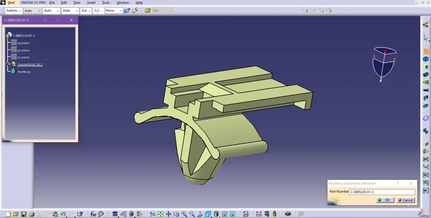
Fig. Mounting Equipment Definition
o Go to the option ‘Mounting Equipment Definition’ to define the connector clip as mounting equipment.
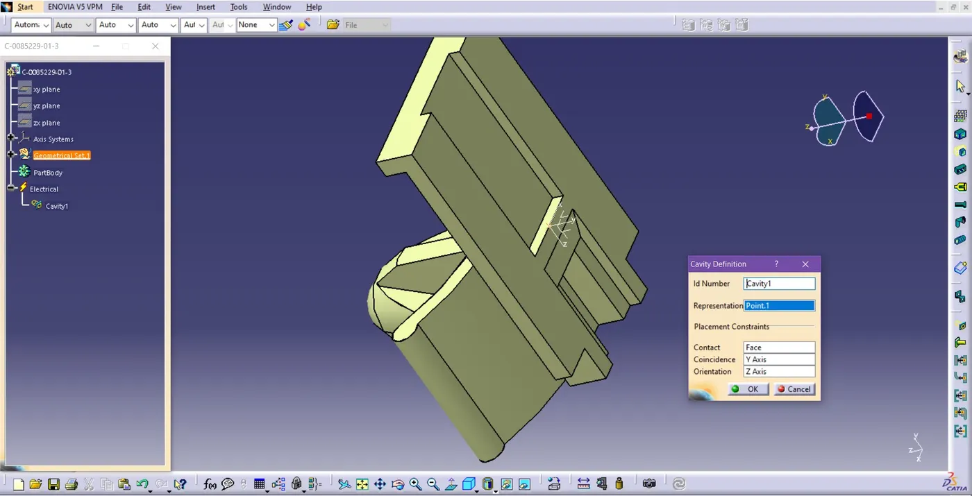
Fig. Define Cavity on Connector Clip
o Go to the option ‘Define Cavity’ and mention the face of Contact, the Y-axis for Coincidence, and the Z-axis for Orientation.
3. Open Electrical Connector Part:
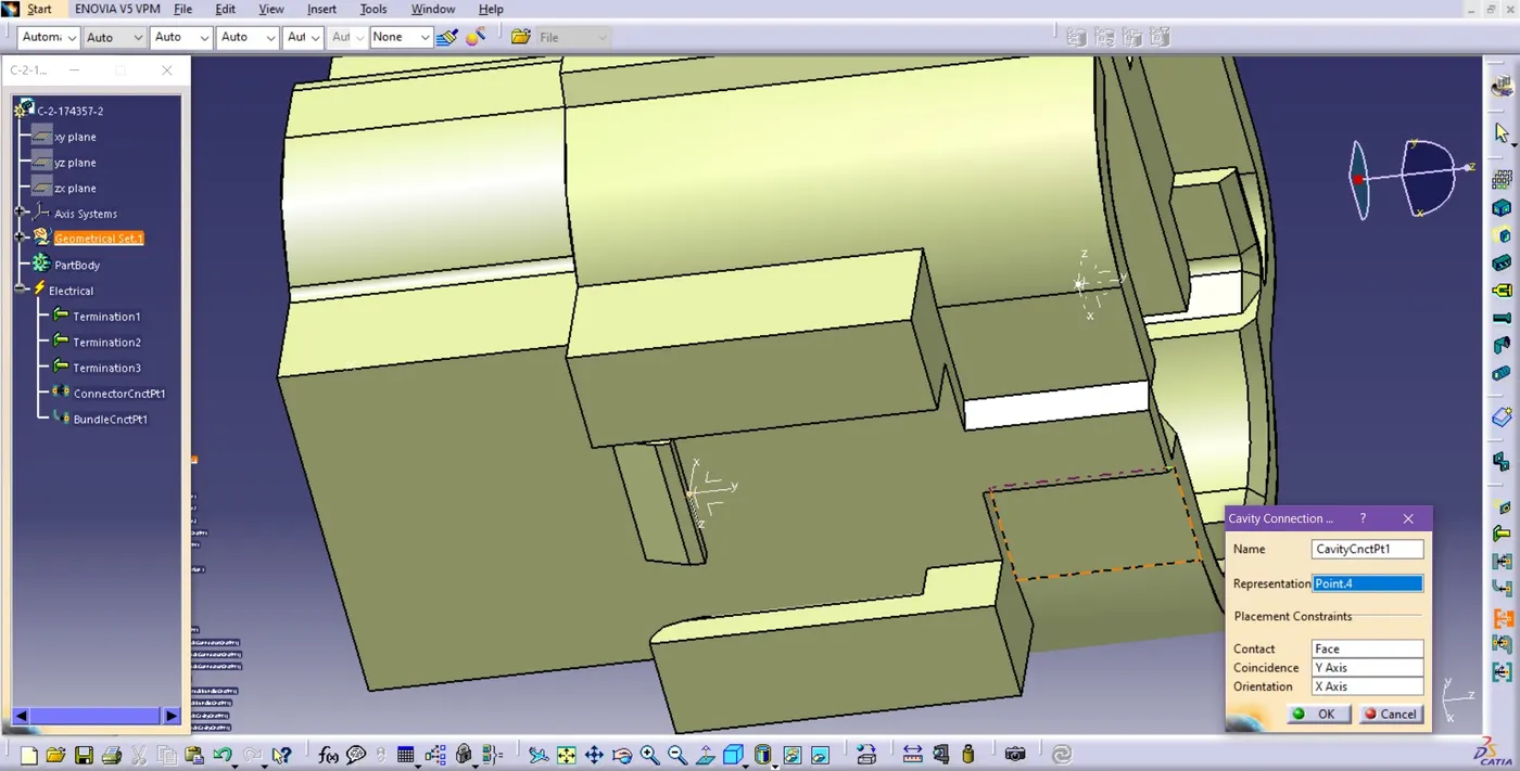
Fig. Define Cavity connector on Electrical Connector
o Go to the option ‘Cavity Connector’ and mention the face of Contact, the Y-axis for Coincidence, and the X-axis for Orientation.
4. Open the Electrical Connector and the Connector Clip & Prepare it for assembly:
Fig. To make the opposite directions of the Connector & Connector’s Connection Axis
o Open the Connector and the Connector Clip vertically side by side to make the axes in opposite directions to mate the parts to each other and make assembly.
o In Connector Clip, Define the ‘cavity’ and in the Connector, define the ‘cavity connection point’ to assemble the connector and connector clip.
Fig. Connect Electrical Devices
o Go to the ‘Connect Electrical devices’ and before clicking both the parts, it shows the connecting point of both the parts(indicates the point in green color).
Fig. Assembled Connector and Connector’s Clip
o We can connect and disconnect the connector and the clip to each other by clicking the option ‘Connect or Disconnect Electrical Devices’ and dragging the part according to requirements (Connect or Disconnect the devices).