Wiring harness design in CATIA V5 - 3D modeling Week 7 Challenge
1. Electrical Definition
1.1. Define Connector
o Electrical Connector Part Number for Harness: C-DT06-08SA-CE13
C-DT06-4S
C-DT06-6S
C-DT06-2S
Open Part to Electrical Part Design Workbench:
1. Switch Workbench to Part Design Workbench-
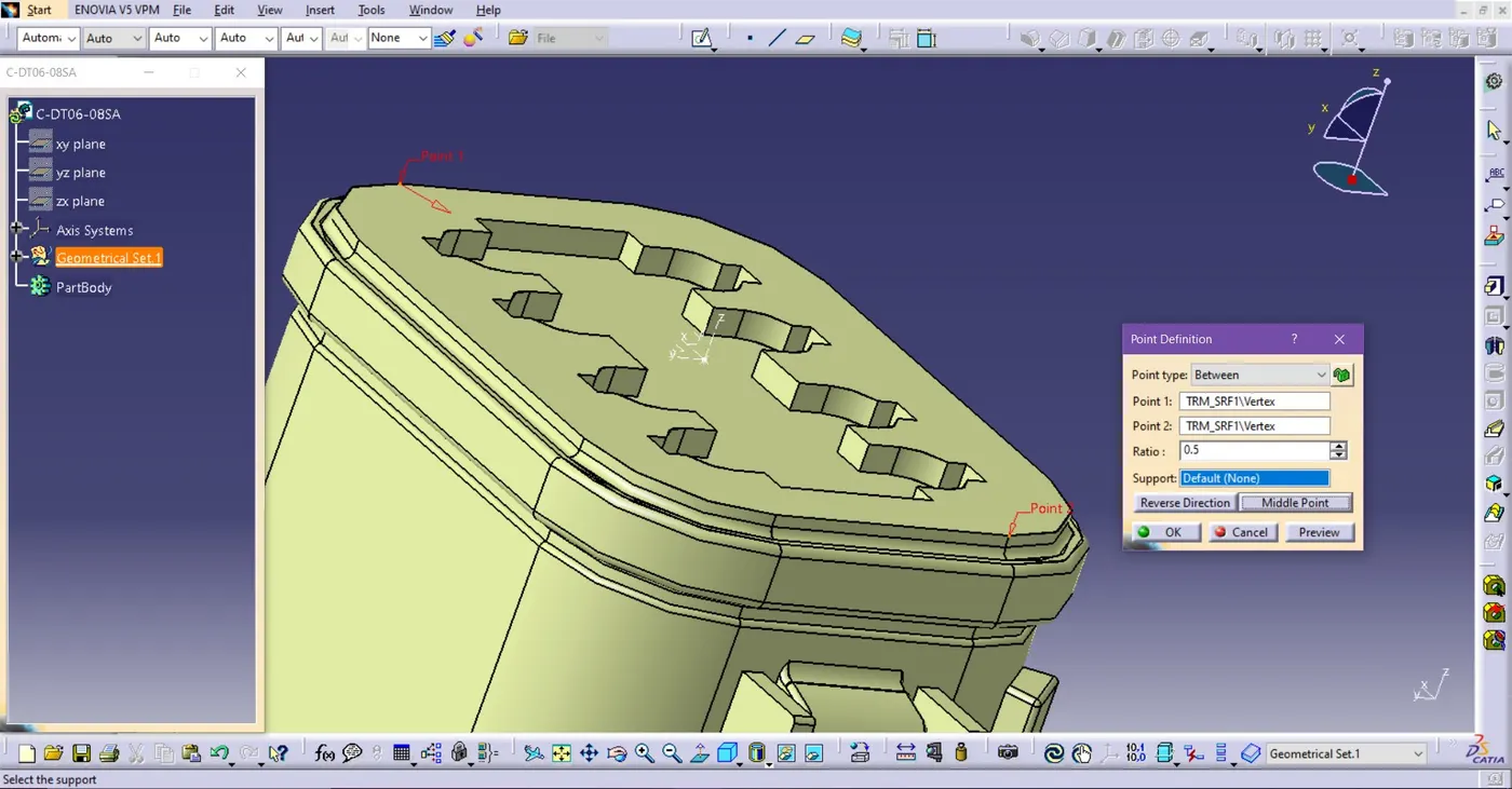
Fig. Make Point on the Connector Connection side
o Go to Point > Opened Point Definition > Choose Points and Set it to Middle point.
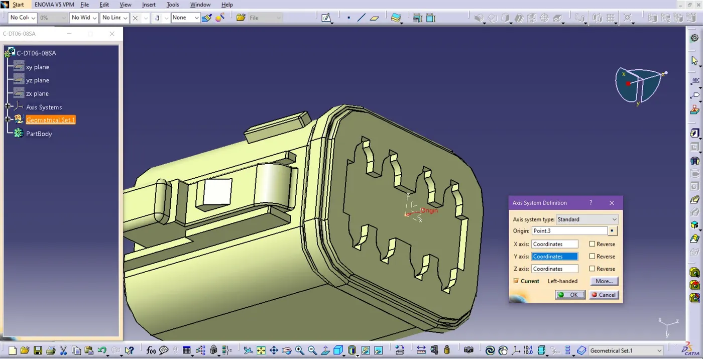
Fig. Axis System Definition of a Connector
o Set the Y-axis is on the direction of the connector’s connection
o Set the X-axis is on the direction of the Connector’s Lock side.
2. Switch Workbench to Electrical Part Design:
o Go to Start > Electrical Part Design to switch to the Electrical Part Design workbench.
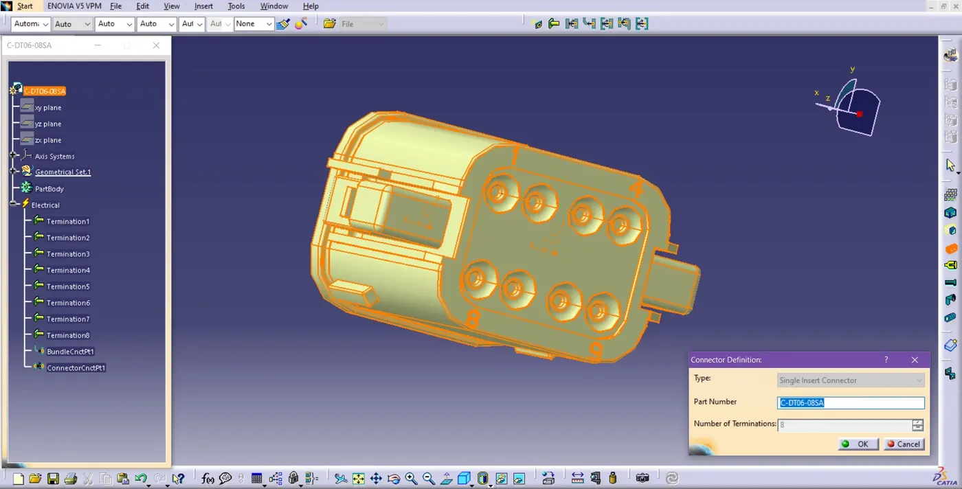
Fig. Connector Definition
o Define the connector with the ‘Define Connector’ Command and mention the number of the wire connections.
3. Define Electrical Properties:
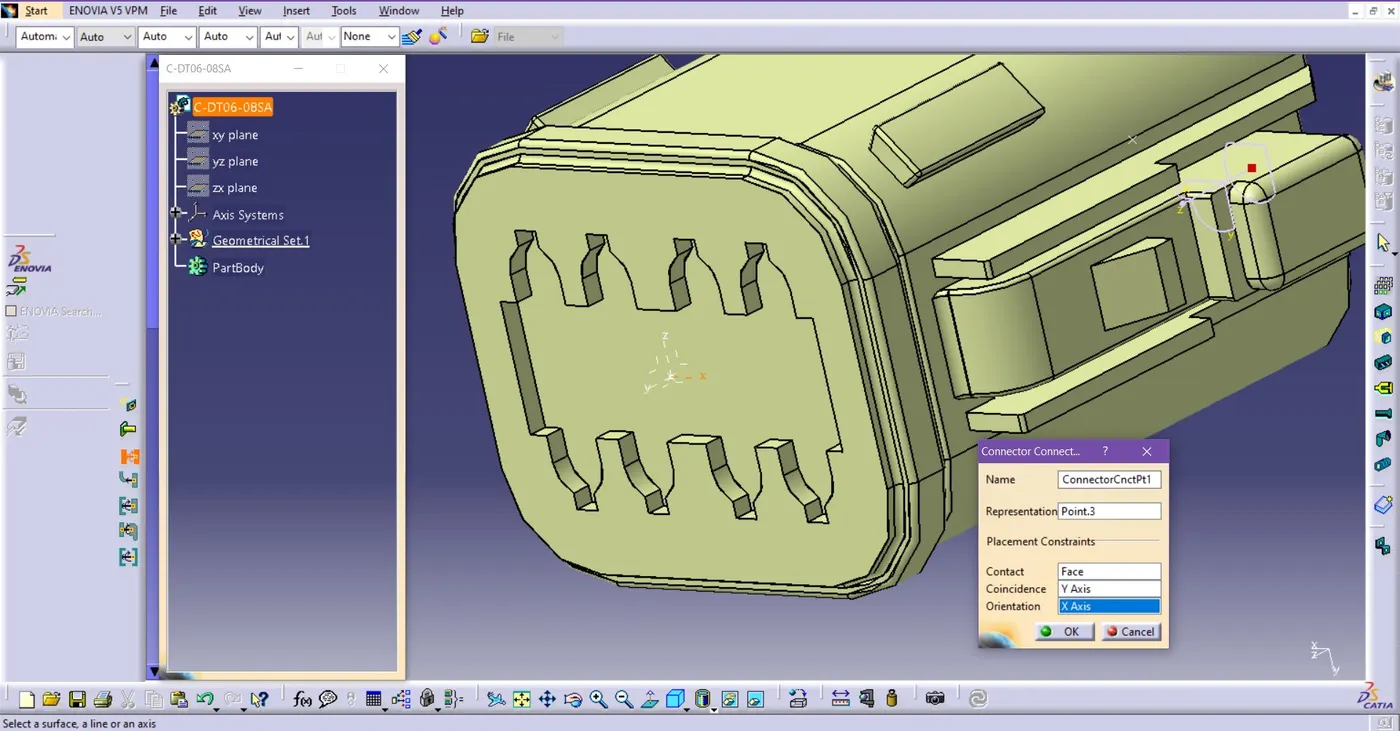
Fig. Define Connector’s Connection Point
o In the Electrical Part Design workbench, the ‘Define Connector Connection point’ command is to define the connector’s connection point, which is defined by ‘Axis system Definition’ at the front side of the connector.
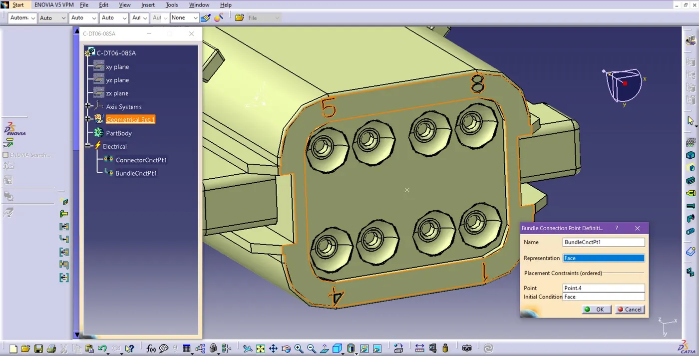
Fig. Bundle Connection Point Definition
o Go to the ‘Define Bundle Connection Point’ Command and choose the face of the connector side at the representation on the dialog box, click on the reference point, and again choose a face for the initial condition to define the bundle connection of the connector
The electrical part (Connectors) is ready for the Electrical Harness Assembly.
2. Bundle Flattening
o Open new product file and change the workbench to Electrical Harness Flattening.
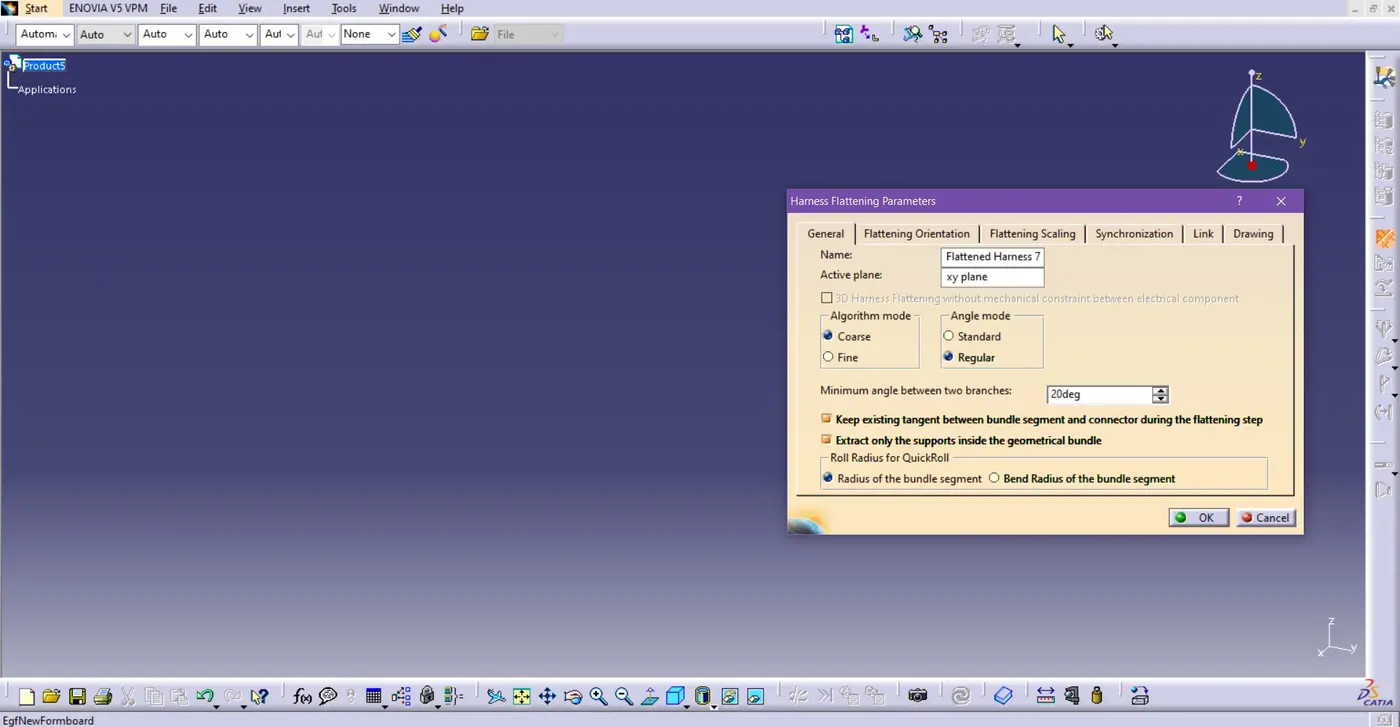
Fig. Harness Flattening Parameter
o In the General tab, Go to Harness Flattening option and rename it as Flattened Harness7.
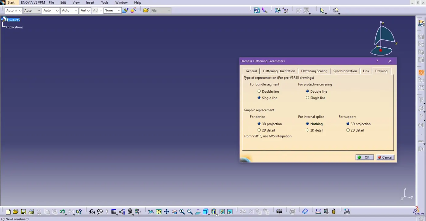
Fig. Drawing settings for Harness
o Change the tab to Drawing
o Choose ‘Single line’ for bundle segment and ‘Double line’ for protecting covering.
o In graphic replacement segment, choose ‘3D projection’ for the device then,
o Choose ‘nothing’ for internal splice and ‘3D projection’ for support
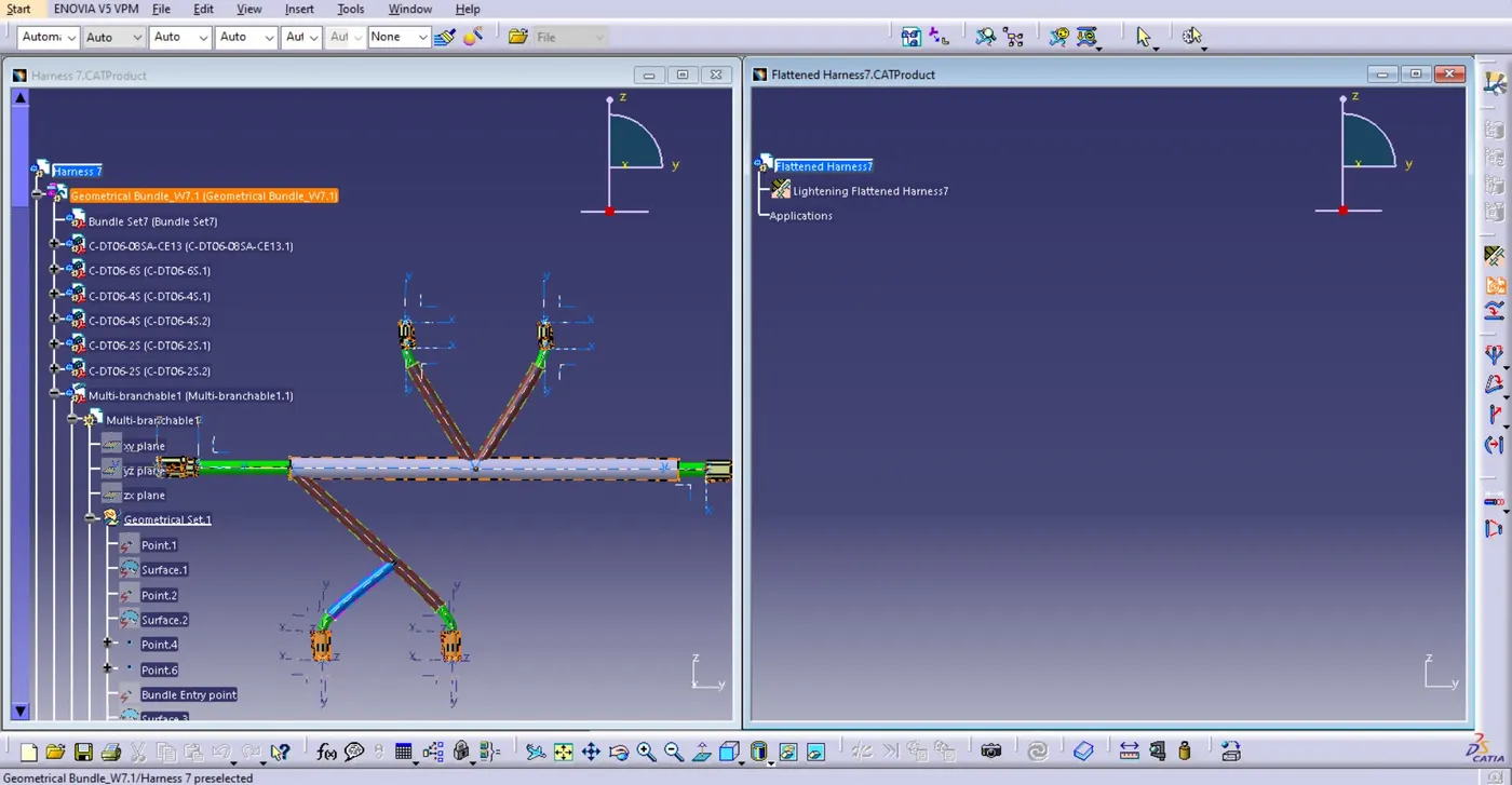
Fig. Extract Bundle for flattening
o Open both files vertically, click Extract in the Flattening Harness file, and click geometrical bundle product in the main design file product tree.
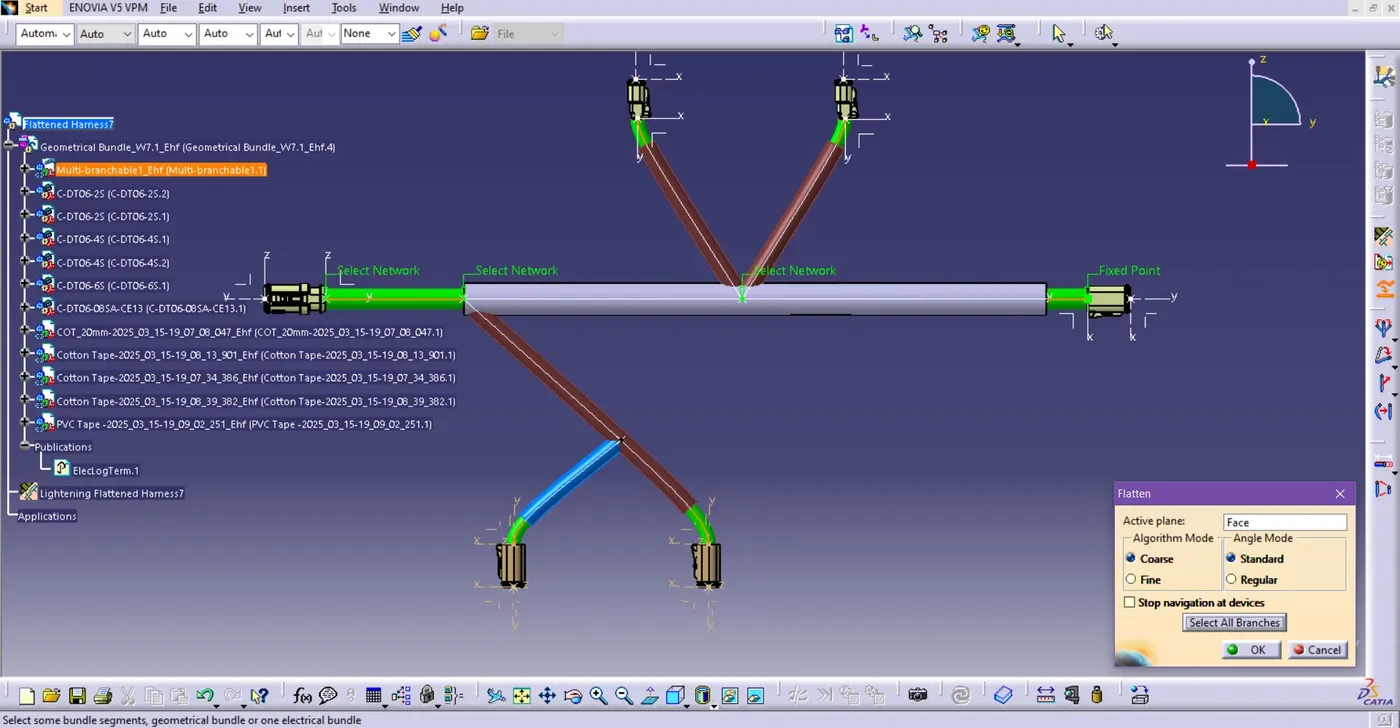
Fig. Extracted geometrical bundle
o After bundle extraction, flatten the bundle.
o Choose the appropriate plane by selecting the face of connector body.
o Select branches you want to flatten or click the ‘Select all Branches’ option.
o Then, Click OK.
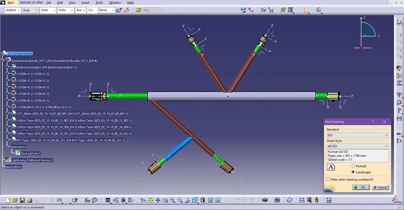
Fig. Flattened Bundle and prepare Drawing sheet
o After Flattening the Harness, Open Drawing sheet.
o Set the new sheet in ‘A0 ISO’ style and ‘landscape’ then, click OK.
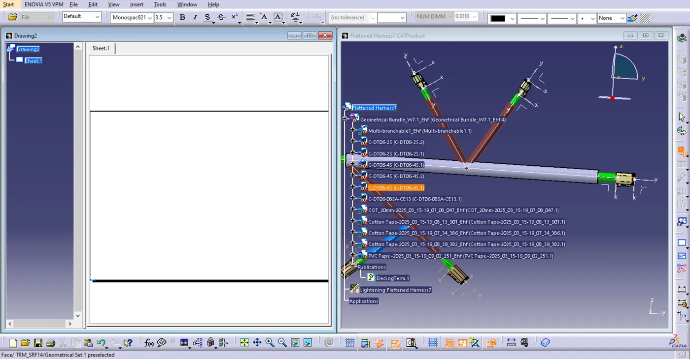
Fig. Add 2D view of Harness for Drafting
o Open drawing sheet and flattened harness vertically.
o To add 2D view of harness to the drawing sheet,
o Select the ‘Front view’ option and select the harness plane by clicking the connector surface.
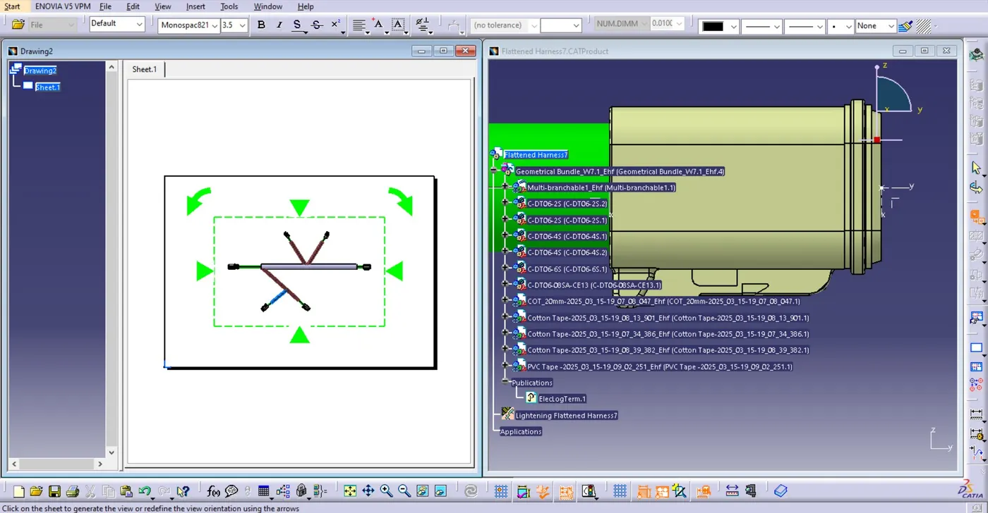
Fig. Set 2D View of Harness
o Set the Appropriate 2D view of the Harness on the Sheet.
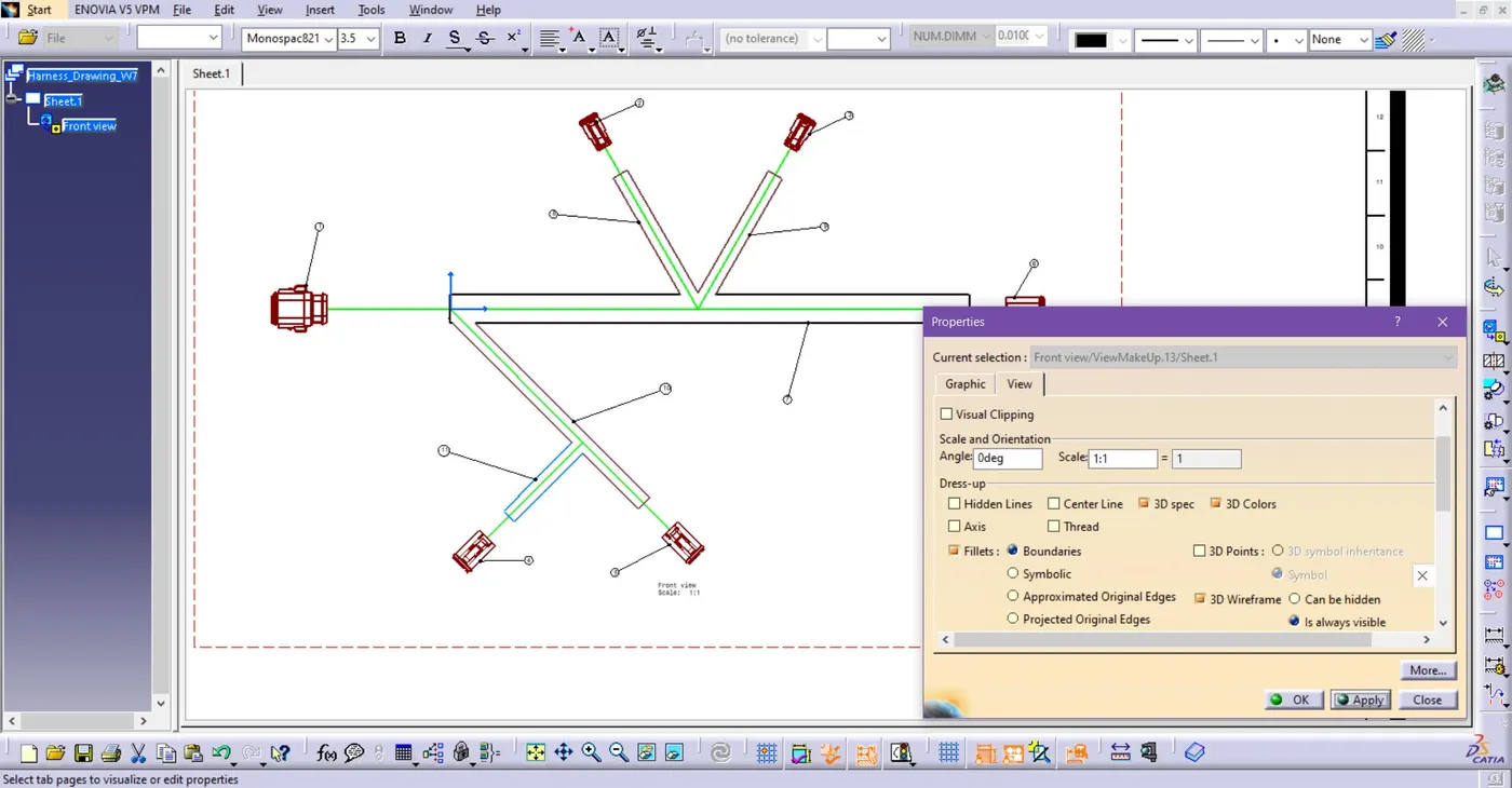
Fig. Drawing View Properties
o Right click on drawing, go to properties > view tab > In Dress-up section, select 3D spec and 3D colours.
o Also select 3D wireframe > Is always visible, and OK.
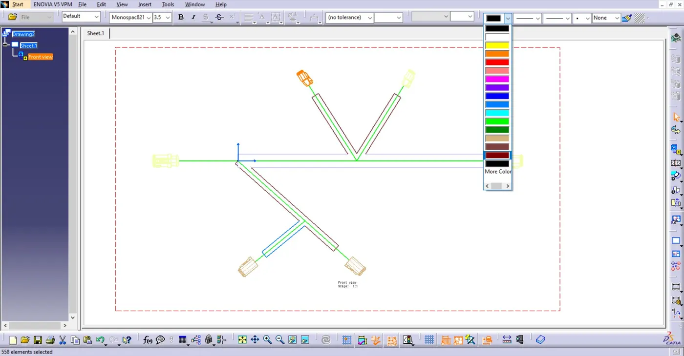
Fig. Change colour for different parts.
o Change the colour of the parts to recognize easily, such as Green for bundle connections, brown for connectors, black for COT tubes, brown for cotton tape and blue for PVC tape.
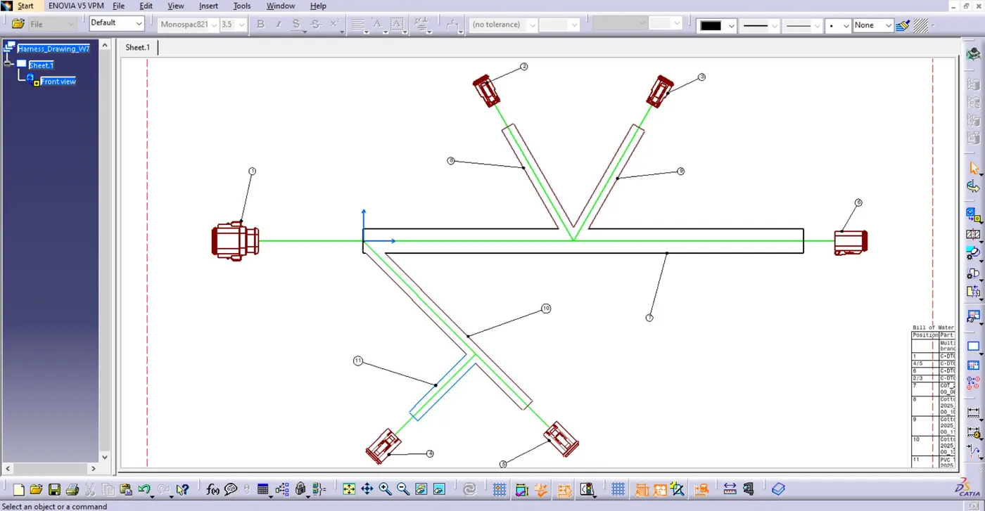
Fig. Bubble for Each Part
o Bubble and numbering to mention the component's position to recognise the information in the Bill of material.
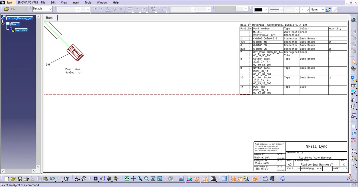
Fig. Bill of Material
o Go to Edit > Sheet Background > select Bill of Material option.
o Determine position of all the parts, colour, quantity and type.