Wiring harness design in CATIA V5 - 3D modeling Week 5 & 6 Challenge
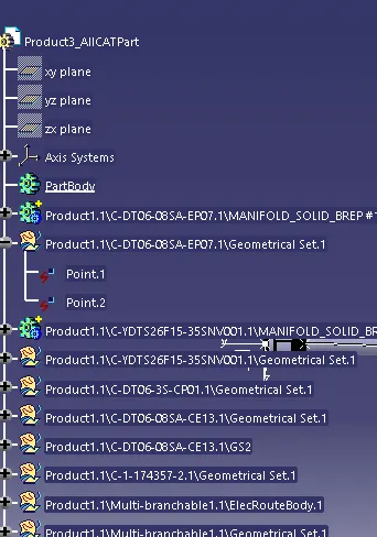
1. The first step is to define the mechanical parts as elctric connectors.
For that in mechanical part design creat the required point and axis system. Next in electric part design the part as connector by selecting Define connector and after that define the connector connection point and bunddle entry point.
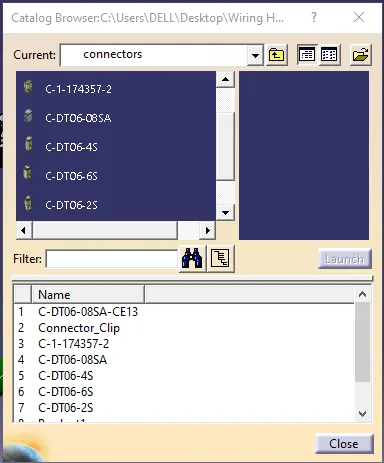
Create a catlogue name it Connector and add the connector to the catlogue.
2. The next step is wiring harness routing.
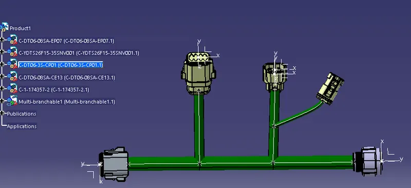
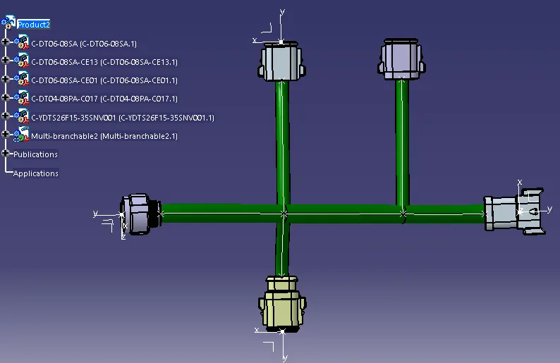
creat a master product and add one more product into it the in electric assembly workbench select the geometrical bundle to convert the mechanical product into electrical. then select multi branchble and selct the 2 outer most connectors. then in electrical harness installation select the add branch point and then on to branch definition create the wiring routing.
Create two wiring harness and name is as Harness A and Harness B
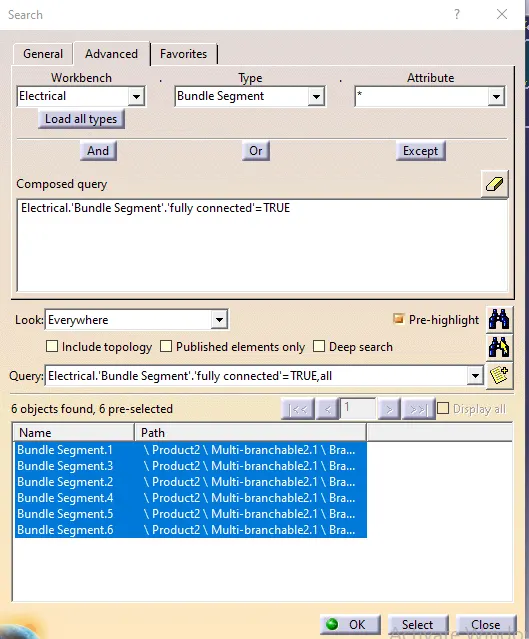
Nex step is to do the continuty check go to the edit then search and in pop up select the electrical workbench and then in type Bundle segment and in attribute select fully connected.
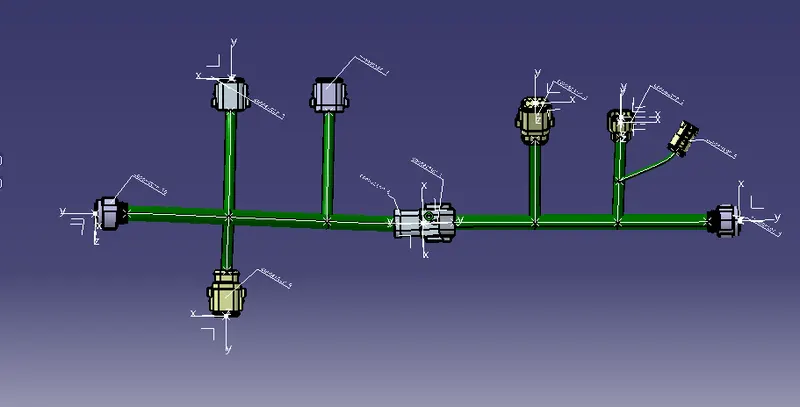
Then add annotation to the connectors select the front view command select the plane and add annotation
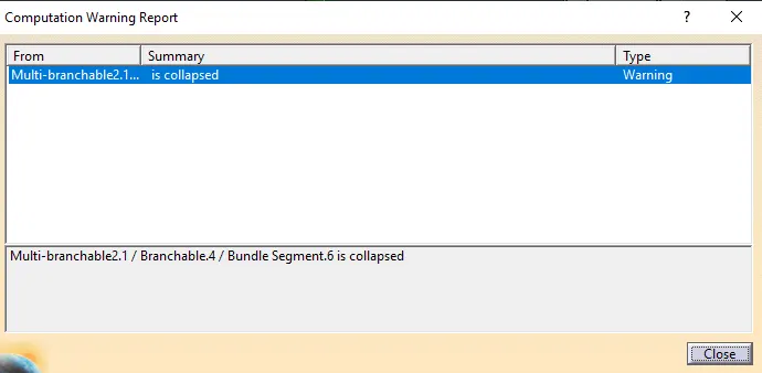
for any bunndle warning we can adjust it by either changing the slack or by moving the brach points
to convert the file intoigs format first go to the tools and select the genarate catpart from product the product will be a catpart now save it and while saving change file type to .igs format