Wiring harness design in CATIA V5 - 3D modeling Week 5 & 6 Challenge
WEEK 5&6_CHALLENGE_WIRING HARNESS DESIGN
OBJECTIVE:
To create Wring Harness Routing & Harness Assembly from the following harness layout in Electrical workbench by using the given cconnectors.
INPUT:
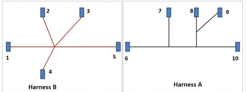
GIVEN CONNECTORS:
1. CONNECTOR_1 - C-YDTS26F15-35SNV001 6. CONNECTOR_6 - C-DT04-08PA-C017
2. CONNECTOR_2 - C-DT06-3S-CP01 7. CONNECTOR_7 - C-1-174357-2
3. CONNECTOR_3 - C-DT06-08SA-CE04 8. CONNECTOR_8 - C-DT06-08SA-CE01
4. CONNECTOR_4 - C-DT06-08SA-EP07 9. CONNECTOR_9 - C-DT06-08SA-EP07
5. CONNECTOR_5 - C-DT06-08SA-CE13 10. CONNECTOR_10 - C-YDTS26F15-35SNV001
Thus above are all the given connectors as of that here mentioned annotations like connector_1,connector_2 etc., and this will get followed in the assembly workbench annotations for the rescpective connector.
TOOL USED: CATIA V5
WIRING HARNESS DESIGN:
STEP_1: ELECTRICAL PART DESIGN WORKBENCH
In this Electrical Part Design Workbench thus the given Mechanical part bodies of the connectors will get converted into Electrical Part by defining its apropriate Electrical defitinions and its Electrical properties. And here by following below as,
1_ Create/Download the CAD data for the required Part 3D.
2_ Create required Geometrical properties by using Part Design Workbench.
3_ Define Electrically like Define as Connector, Backshell, Supporting, & Mounting Equipment,etc.,
4_ Define its required Electrical properties like Define as Connector connection point, Bundle connection point, Cavity connection point & etc., after that add all the cad data in to the catalog browser itself with electrically defined.
And here thus the given Conectors are become Electrically defined by applying the above all and the followings are,
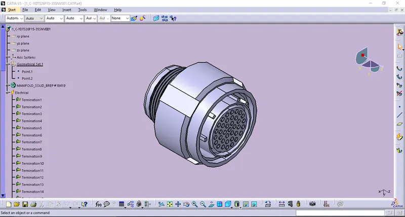
1. CONNECTOR_1 - C-YDTS26F15-35SNV001
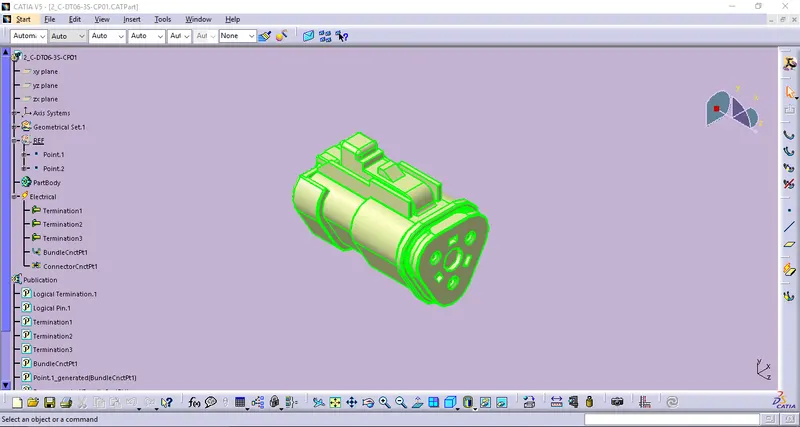
2. CONNECTOR_2 - C-DT06-3S-CP01
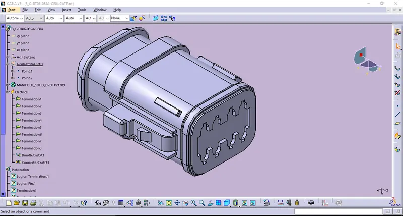
3. CONNECTOR_3 - C-DT06-08SA-CE04
4. CONNECTOR_4 - C-DT06-08SA-EP07
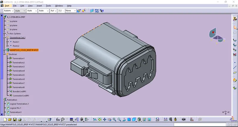
5. CONNECTOR_5 - C-DT06-08SA-CE13
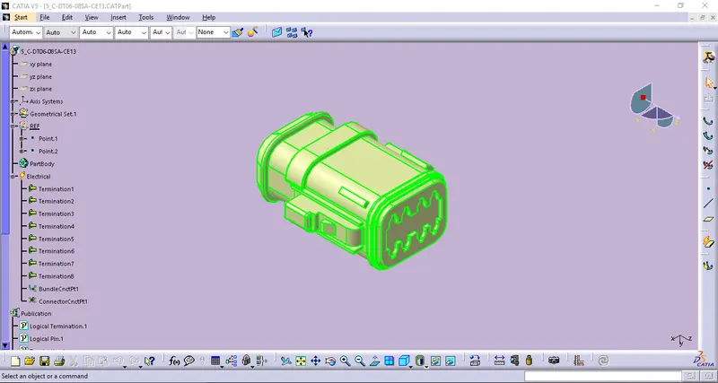
6. CONNECTOR_6 - C-DT04-08PA-C017
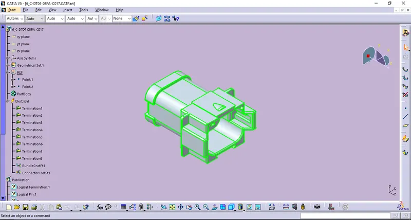
7. CONNECTOR_7 - C-1-174357-2
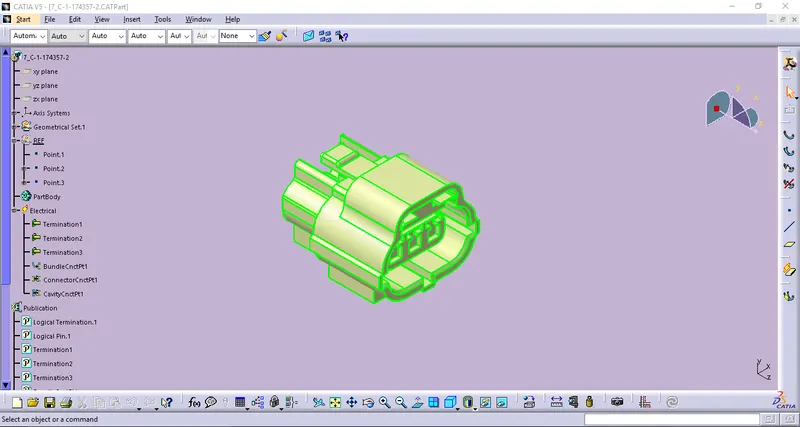
8. CONNECTOR_8 - C-DT06-08SA-CE01
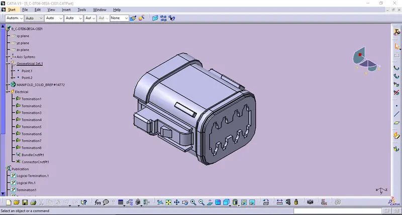
9. CONNECTOR_9 - C-DT06-08SA-EP07
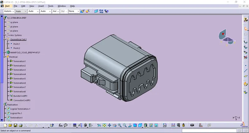
10. CONNECTOR_10 - C-YDTS26F15-35SNV001
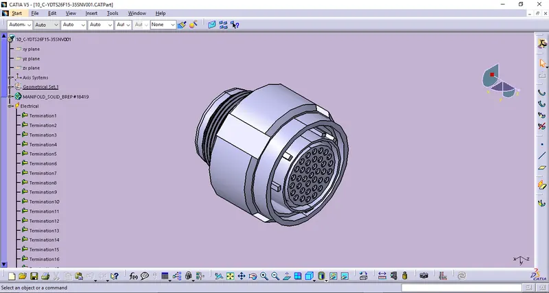
STEP_2: ASSEMBLY WORKBENCH
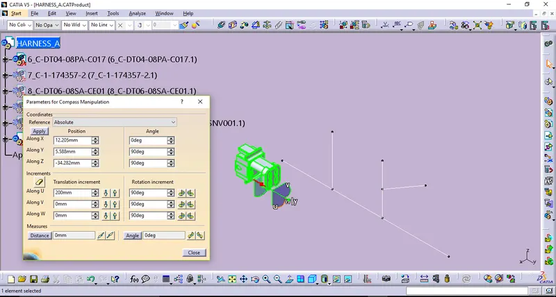
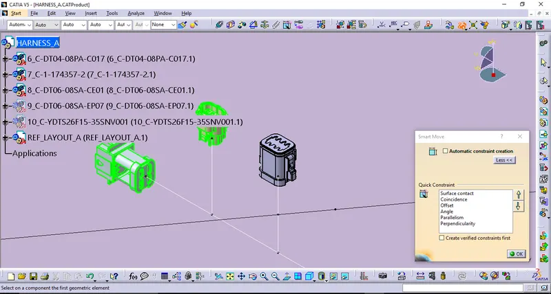
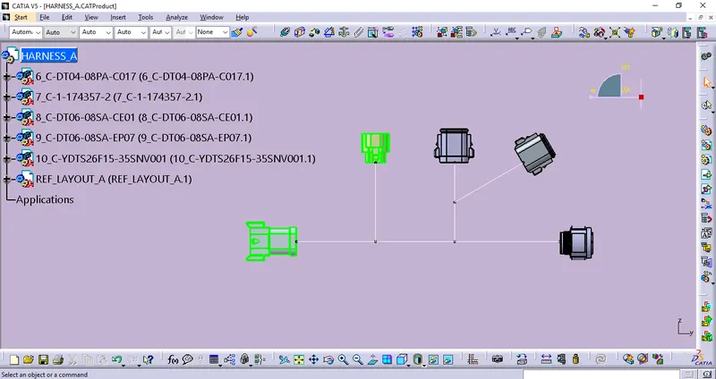
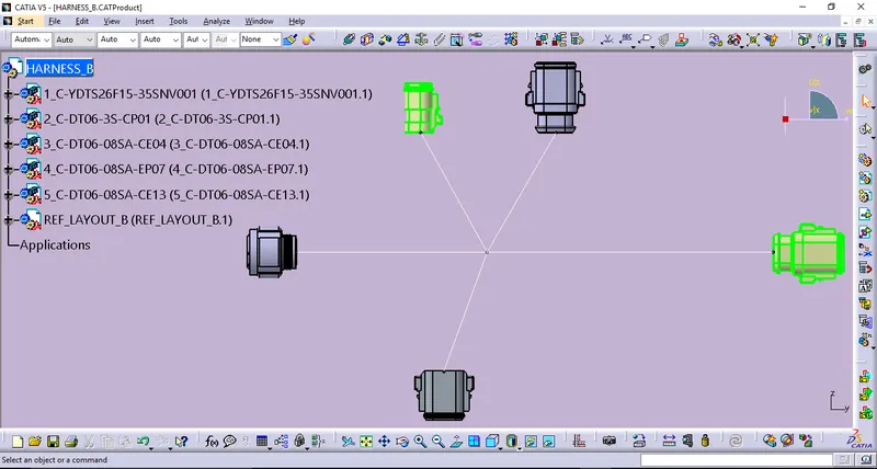
In this Assembly Workbench(Mechanical) has to be widely used to alocate the Electrically defined parts in the proper positions based on the layout. And here few commands are used to locate the electrical parts by using Move toolbar commands like Manipulation, Snap, Smart move and by using the Translation/Rotation by using Compass. In before start positioning ensure that all the Electrical parts add into the Product file and keep following measurements in the given layout, here I create a layout Sketches by using the Part workbecnch in the apropriate dimensions which will helps us easier to loacate And the followings are,
1_HARNESS A POSITIONING:
2_HARNESS B POSITIONING:
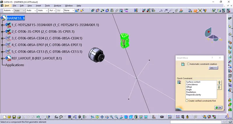
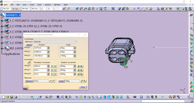
STEP_3: ELECTRICAL HARNESS ASSEMBLY
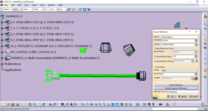
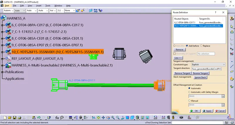
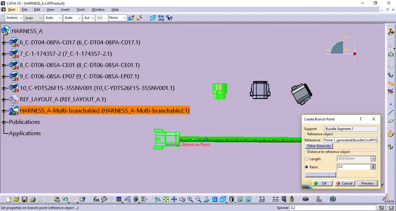
In this Electrical harness assembly workbench which will used creating harness routings by defining the Mechanical product file becomes converted as Electrical Harness by clicking Geometrical bundle. Then by using multi branchable command start routing the harness assembly design. And the followings are,
HARNESS_A & HARNESS_B ROUTING:
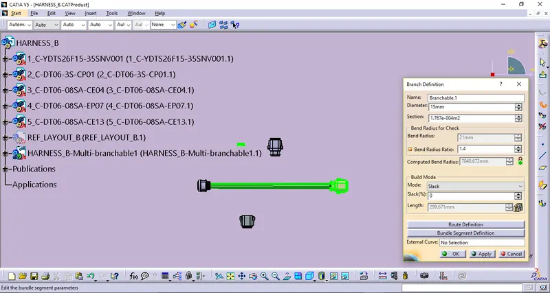
Defining Branch definition.
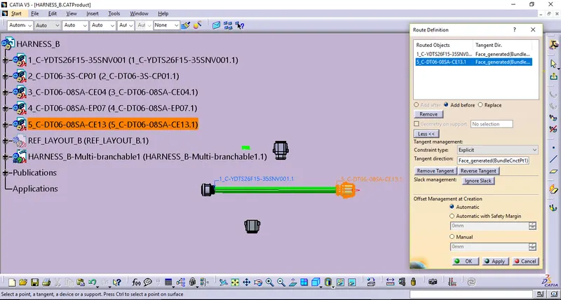
Defining Routing definition.
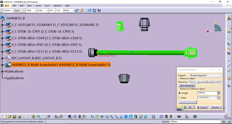
Defining Create Branch point.
Defining Branch definition.
Defining Routing definition.
Defining Create Branch point.
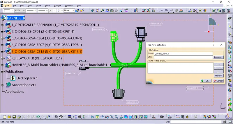
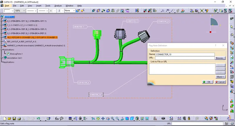
ANNOTATIONS:
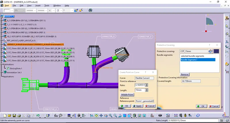
Defining protective covering.
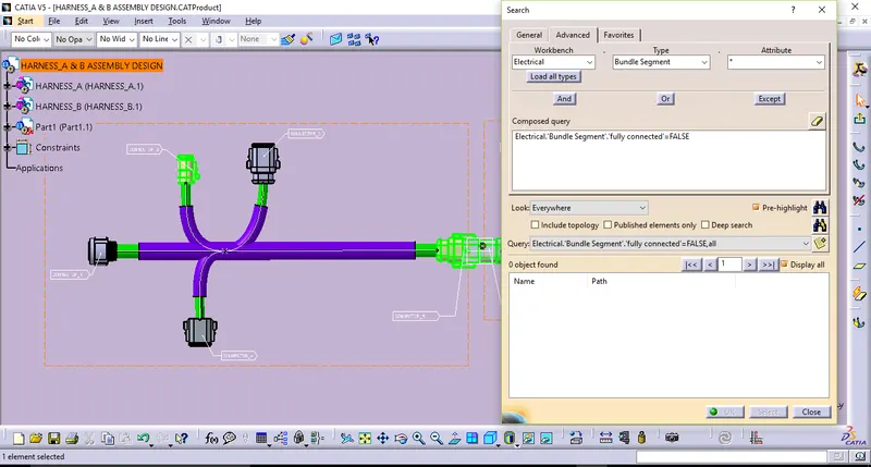
STEP_5: BUNDLE CONTINUITY CHECK
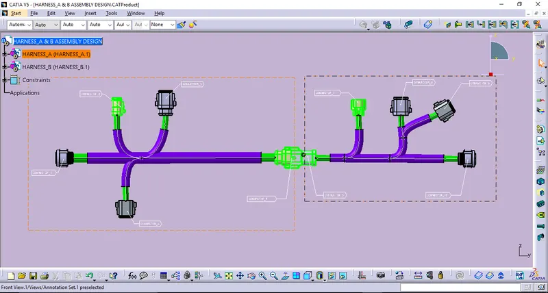
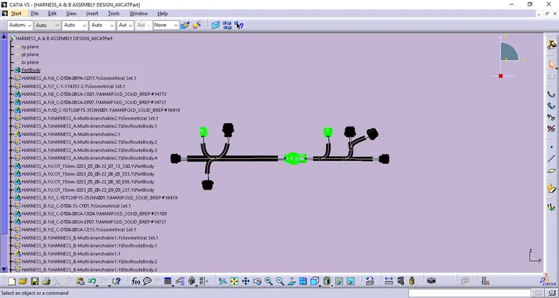
STEP_6: HARNESS_A & B ASSEMBLY
STEP_7: GENERATE CATPART FROM HARNESS DESIGN
CONCLUSION:
Thus the Wiring Harness design and the Harness assembly between Harness A & Harness B are done by following the given layout & using given connectors in CATIA V5 Electrical Harness Module. Also Bundle warnig checked & CATPart creations done.