Wiring harness design in CATIA V5 - 3D modeling Week 5 & 6 Challenge
Wiring harness design in CATIA V5 - 3D modeling Week 5 & 6 Challenge
AIM:
Let, we have provided the harness layout as below and accordingly we have to route it. For that we have to make assumption for harness bundle diameters and use DT connectors.
OBJECTIVES:
- Check the bundle Continuity. Add snap of result in submission.
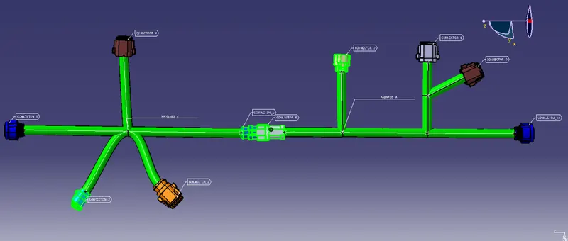
- Add annotation to all connectors. Make an assumptions for annotations like connect 1 , 2 etc.
- Check for the bundle warning. Add snap.
- Generate CAT.part of harness assembly and convert is in. igs format.
CONNECTOR DEFINITION:
DESIGN METHODOLOGY:
- Create/download connector in 3D
- Create required geometrical parameter
- Define part as connector

- Define bundle connection point

- Define connector connection point

DESIGN PROCEDURE:
1. CREATE/ DOWNLOAD CONNECTOR IN 3D:
Its a first stage of design wiring harness assemble. To create or download the connector in TE connectivity webside.
2. CREATE REQUIRED GEOMETRICAL PARAMETER:
Its is second stage of design wiring harness assemble. In this stage create a point and axis were the connection point place.
3. DEFINE PART AS CONNECTOR
In this stage fix the connector into electrical part design. It is convert the mechanical part into electrical part. After create a geometrical parameter then open the electrical part design workbench. Then select the connector obtion it open dailogbox mention the how many terminal present in connector then give ok. Now it converted into electrical properties.
4.DEFINE BUNDLE CONNECTION POINT :
After convertion mechanical into electrical part give a connection to bundle place. Select the define bundle connection point obtion it open a dialogbox give a name to the feature and representation of the feature and select the point were the bundle to place.
5.DEFINE CONNECTOR CONNECTION POINT :
In this stage give a connection to connector using define connector connection point obtion. select the connector connection point obtion it will open a dialogbox. In that dialogbox give a name to connector select the point and axis were connection to place.
GIVEN DATA CONNECTOR:
CONNECTOR 1:
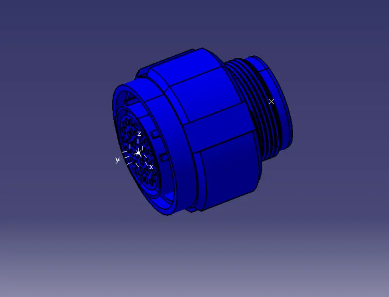
CONNECTOR 2:
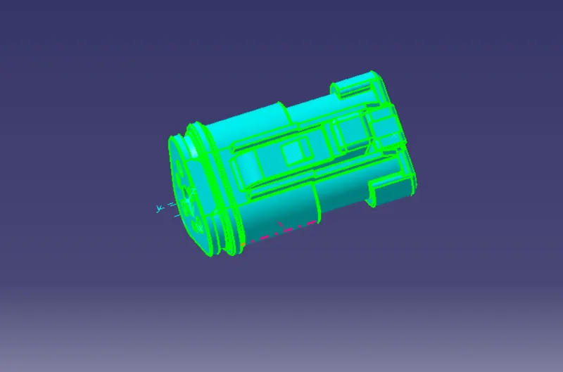
CONNECTOR 3:
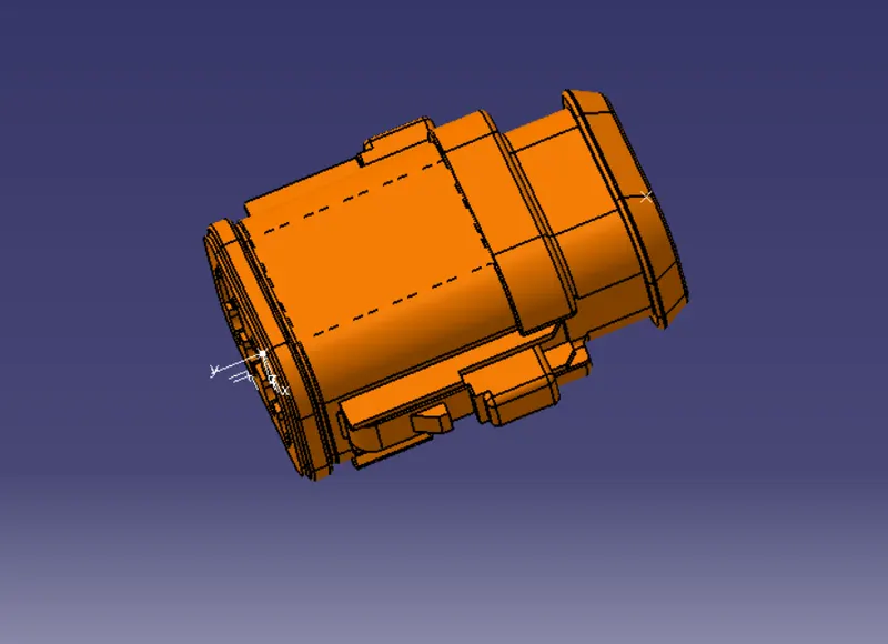
CONNECTOR 4:
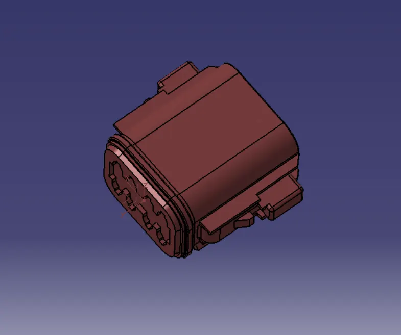
CONNECTOR 5:
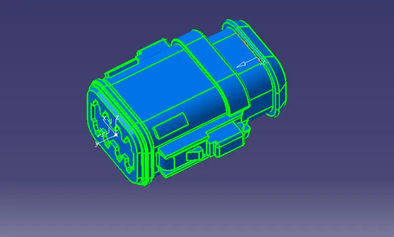
CONNECTOR 6:
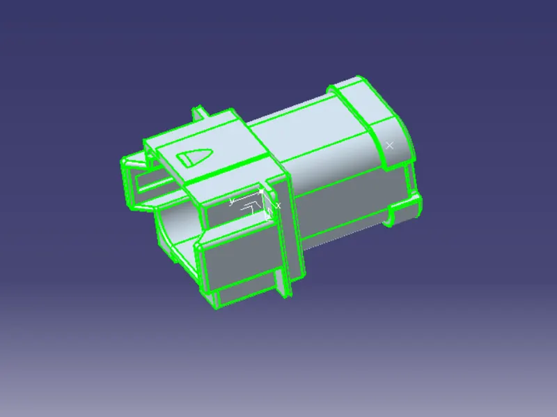
CONNECTOR 7:
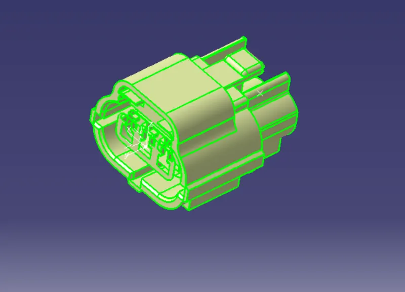
CONNECTOR 8:
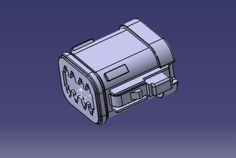
CONNECTOR 9:
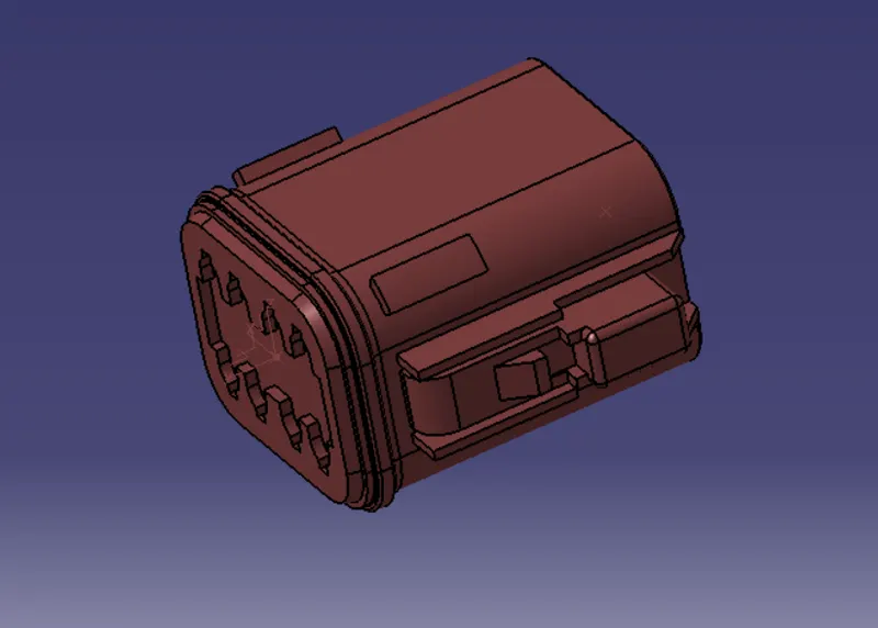
CONNECTOR 10:
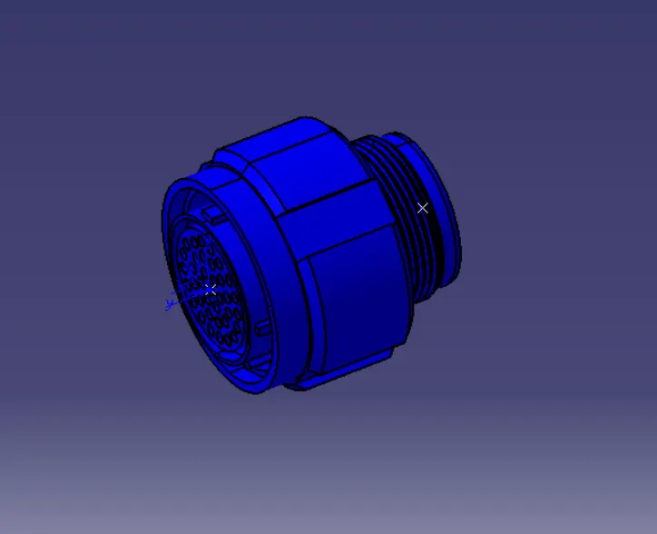
HARNESS ROUNTING:
After defining the connector has given data to make routing to the connector.Then switch to electrical harness assembly workbench with use of existing component command place the connector into the workbench. From the input layout separate connector with help of compass. After separate the connector product file to converted into electrical part. For that select the geometrical bundle and the product file now it converted electrical. After convertion of electrical file create a bundle to the connector. Then go the multibranchable point Route the bundles And suiatable break points with respect to the given Diagram.
HARNESS A:
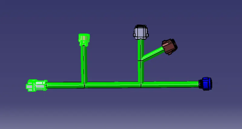
HARNESS B:
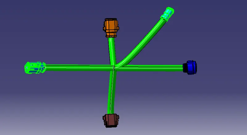
CHECKING THE BUNDLE CONNECTION:
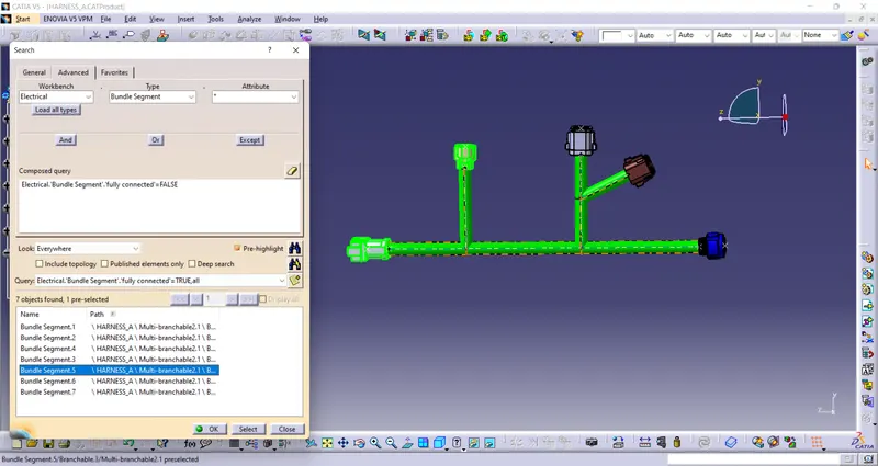
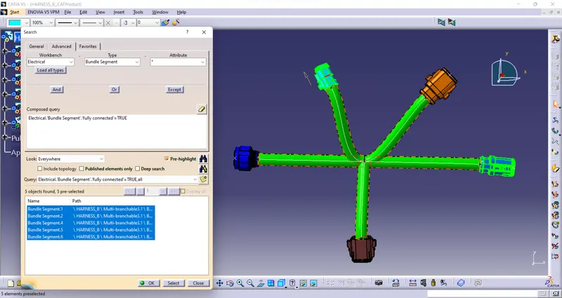
By Clicking the Ctrl+F Key we go the pop up .Then Go To The Advanced & Select the Electrical workbench & select the bundle segment on type & go to the attributes select the Fully Connected as shown on below figure.
WIRING HARNESS ROUNTING:
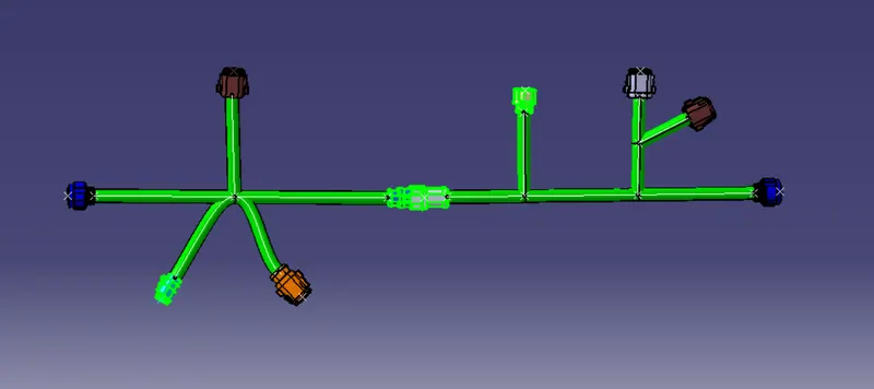
Now open new product file place the created harness into the product file. We have to go in Electrical Assembly Design to connect both the harnesses electrically. So for that, select the option 'connect electrical devices' and both the harnesses will get connected electrically as below.
ANNOTATION:
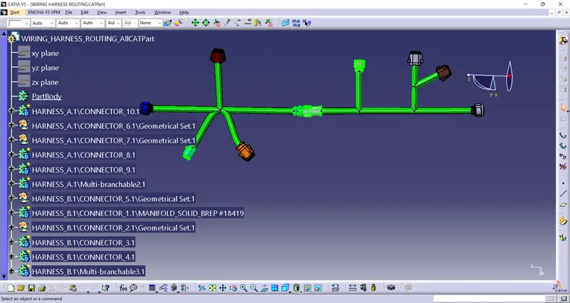
GENERATED CAT PART INTO PRODUCT:
CONCLUSION:
Created the wiring harness routing with required from the layout and converted to cat part to product as well as evaluate the bundle connectivity.