Week 8 - Challenge 2 - Switch Bezel Design
WEEK 8 CHALLENGE 2 SWITCH BEZEL DESIGN
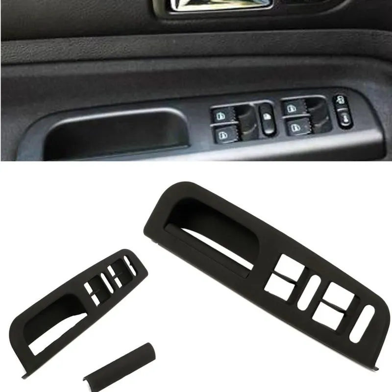
Switch bezel is a one of the plastic component in the car. In switch bezel has asthetic surface in top surface at bottom has class b and class c surface.To begin with tooling axis for class a surface.With the referance of class A it created class B surface. And with referance of class A and class B it created class C surface.
TOOLING AXIS
- It is the first stage of to create surface modeling of this design.
- Before create a tooling axis have to create dummy tooling axis.
- For to create dummy tooling axis take referance with class A surface with help of intersect tool at the one plane
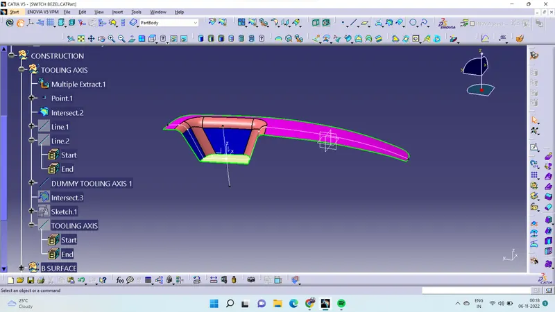
(DUMMY TOOLING AXIS)
- Then select the other side of plane and select position sketch draw the bisecting line give angle to it.
- And rename the line which have created name as main tooling axis.
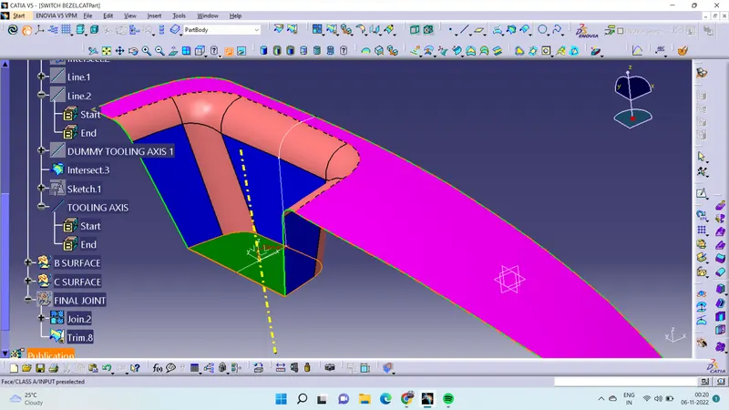
(TOOLING AXIS)
CLASS B SURFACE
- It's a second stage of this design and it look like a copy of class A.
- Extract the class A from bezel rest, wall and base.
- Then untrim which have extract from the class A surface.
- After done the untrim then extrapolate the surface.
- At the given thickness of component offset the surface.
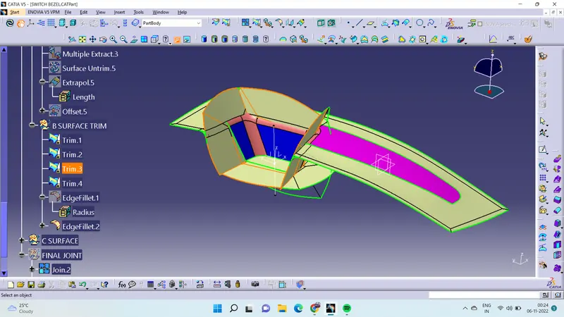
(BEFORE THE FINAL TRIM)
- With use of trim tool remove the unwanted surface then form class B surface.
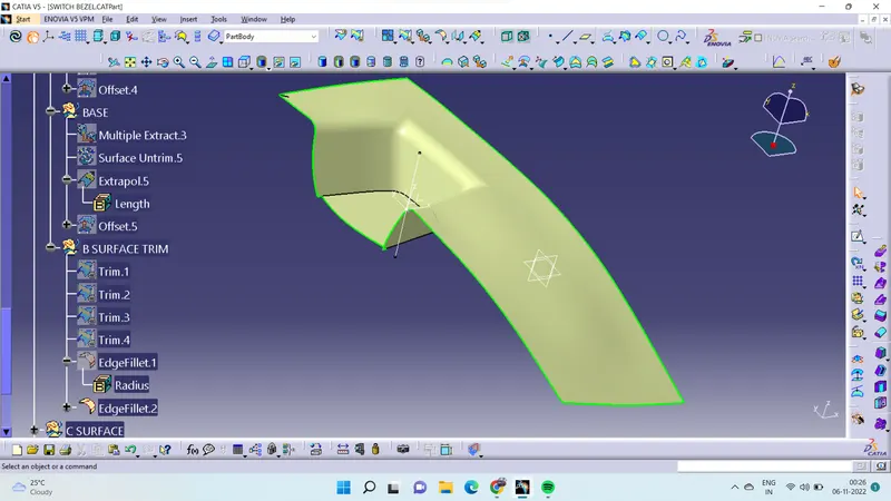
( CLASS B SURFACE)
CLASS C SURFACE
- Class C surface is the giving thickness to the class A and class B surface.
- To create the class C surface for that extract the boundary of class A surface.
- After extract the boundary of the class A surface then go to sweept tool in that select the profile type and select the subtype as WITH DRAFT DIRECTION.
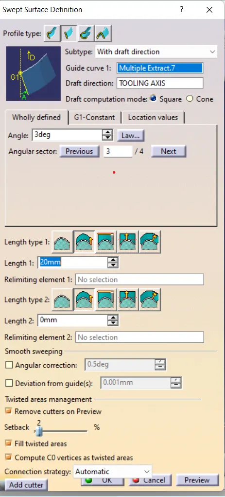
(SWEEPT TOOL)
- In guide curve obtion select the boundary of the class A surface which have extract and in draft direction obtion select the tooling axis.
- And give the maximum draft angle of 3 deg.
- And select side which have sweept to create then give OK.
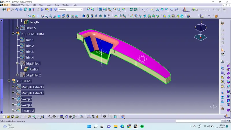
(CLASS B SURFACE)
FINAL TRIM
- In final trim have to merge the class A and class C surface for that use join tool select the two surfaces.
- After that have to remove the unwanted surfaces for that go to trim tool select the class B and class C surfaces.
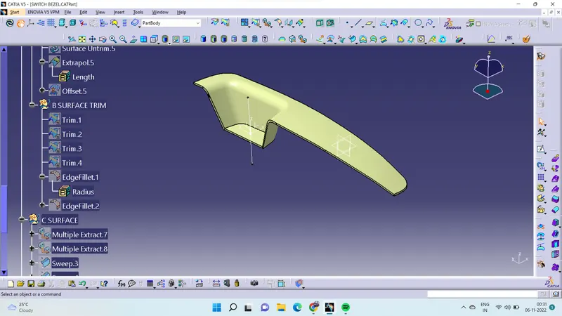
(SURFACE MODELING OF SWITCH BEZEL)
- To make solid module then go to part workbench then select the close suface and select the surface module give OK then it form in solid module.
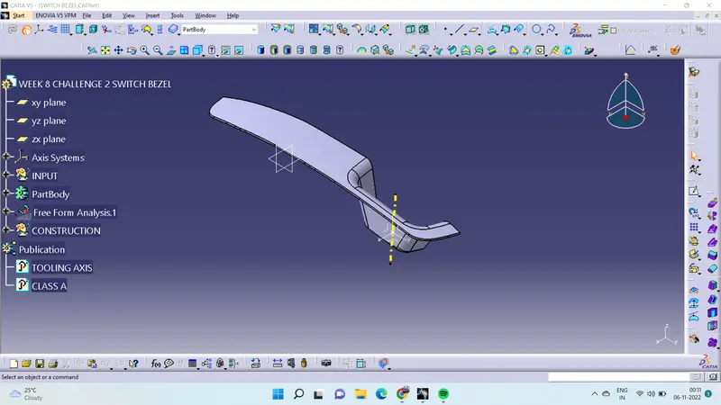
(SOLID MODELING OF SWITCH BEZEL)
DRAFT ANGLE ANALYSIS
- Draft angle analysis tool used to analysis draft of the object.
- To check the draft angle then go to insert in that go to analysier and select the draft angle analysis.
- Then pick the compass drage and merge to the tooling axis.
- Before going to analysis to ensure that it's in customize view parametries in that select the material mode.
- And click the surface then it will show the draft angle analysis.
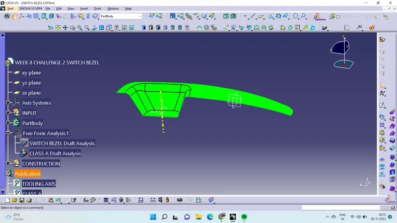
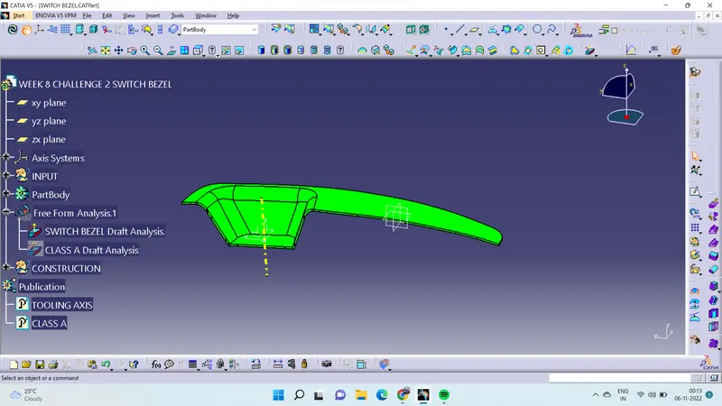
(DRAFT ANGLE ANALYSIS OF CLASS A SURFACE) (DRAFT ANGLE ANALYSIS OF SWITCH BEZEL)
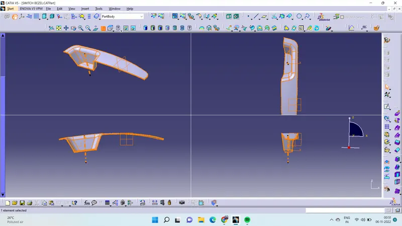
MULTIPLE VIEW
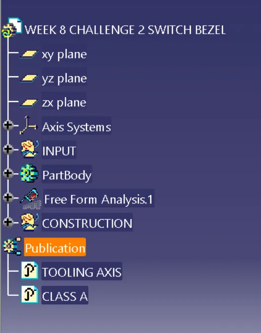
TREE STRUCTURE