Wiring harness design in CATIA V5 - 3D modeling Week 5 & 6 Challenge
Q1. Route the following harness layout in Electrical workbench. Make assumption for harness bundle diameters. Use the connectors provided. After completion of routing,
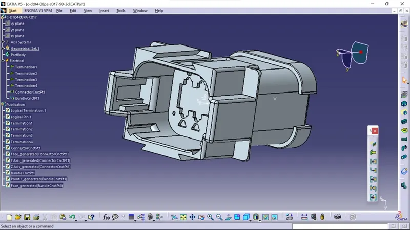
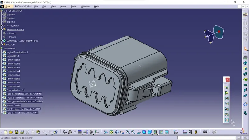
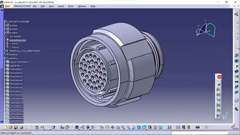
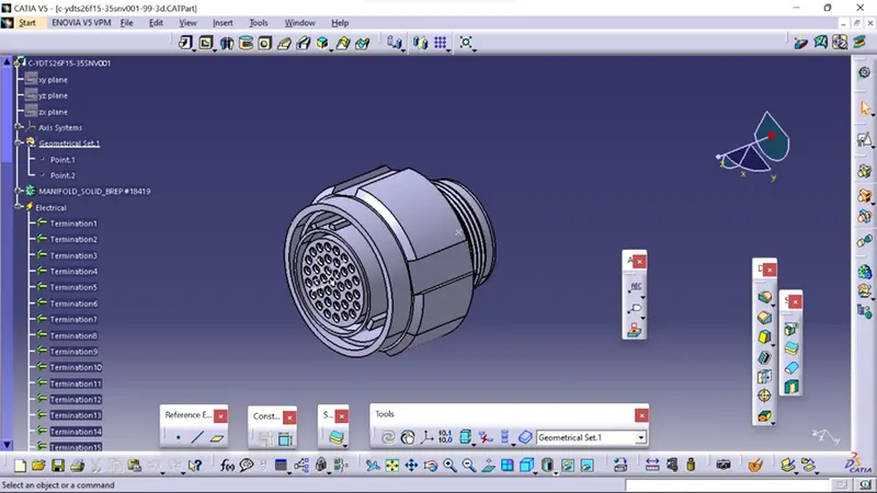
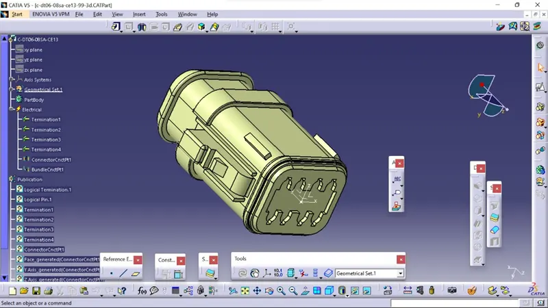
First we have to Create geometric and electrical definitions for all electrical connectors that will be used in the wiring harness.
Connectors used in Harness_A
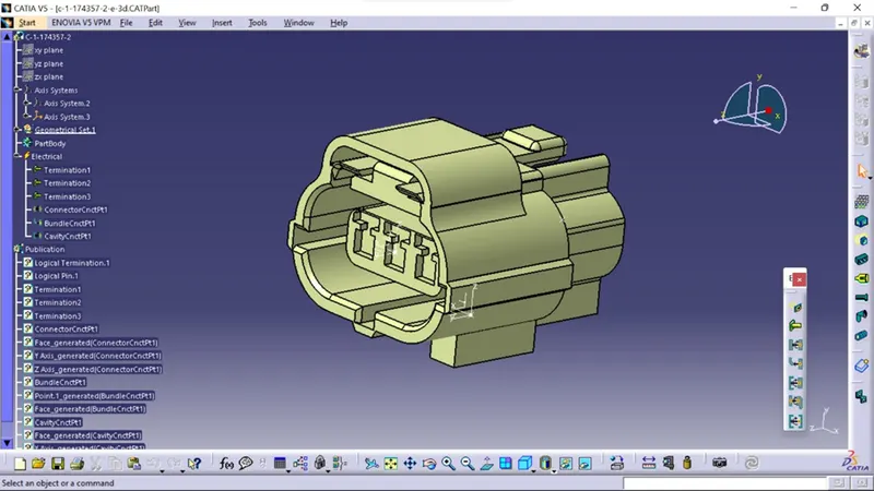
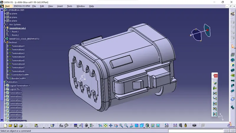
Connectors used in Harness_B
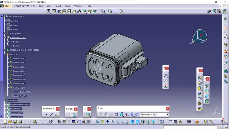
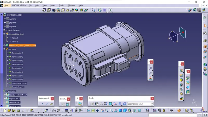
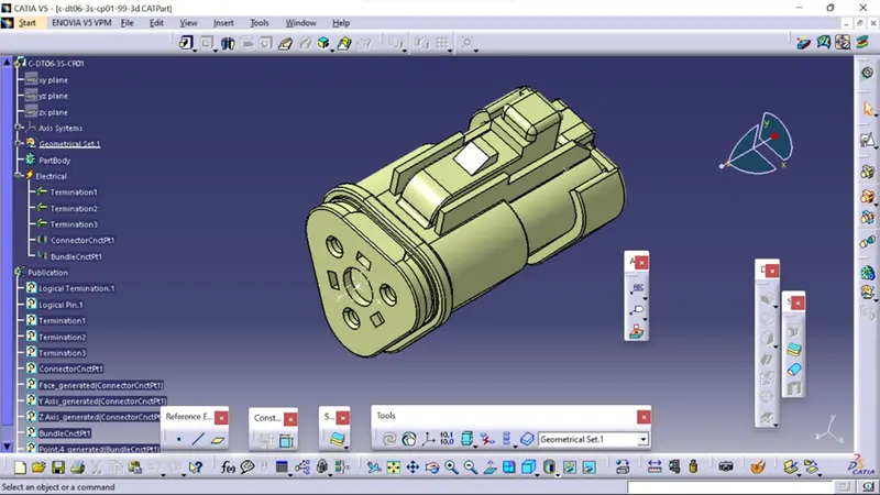
after that Using the electrical harness workbench in CATIA V5, create harness A and harness B as shown below.
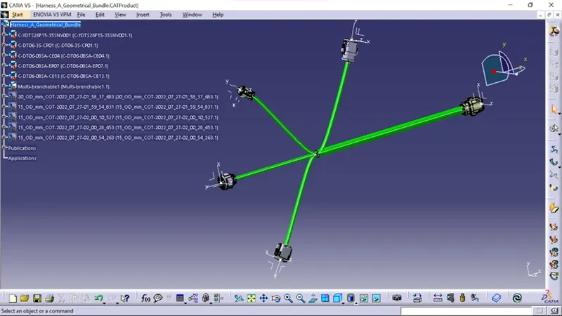
First, all of the connectors are placed in their proper positions. Second, bundle segments with branch points and branches are created between the connectors, as shown below.
Bundle diameters of 15mm, 12mm, 8mm, and 5mm are assumed for various bundle segments. For all bundle segments, the bend ratio is 1.4 and the slack is zero percent.
after bundle connection of Harness_A
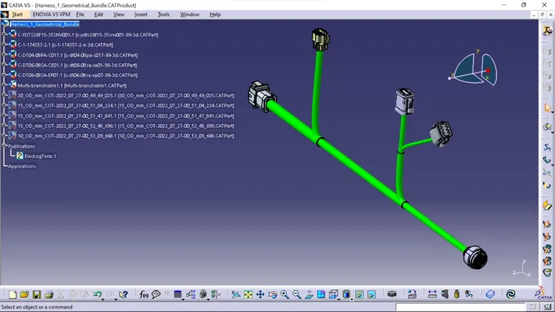
Harness bundle connection_B
ollowing the creation of Harness A and Harness B, the bundle continuity must be checked.
To begin, ensure that multi-branchable is selected, then navigate to Edit>Search>Advanced>Electrical Workbench>Type-Bundle Segment>Attribute-Fully Connected.
In this step, we must electrically connect Wiring Harness A and Harness B. A few steps must be taken in order to electrically connect the two harnesses.
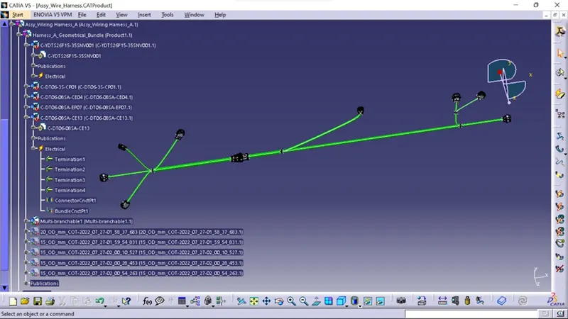
To begin, create a new product file in CATIA and rename it "Assy Wire Harness."
Second, insert harness A and harness B into the newly created product file to create the final harness assembly. Once inside the electrical assembly design workbench, connect the male and female connectors as shown below.