Wiring harness design in CATIA V5 - 3D modeling Week 5 & 6 Challenge
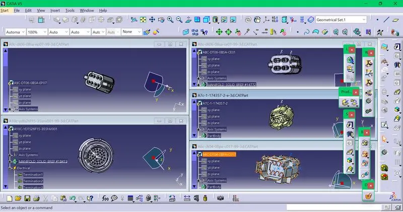
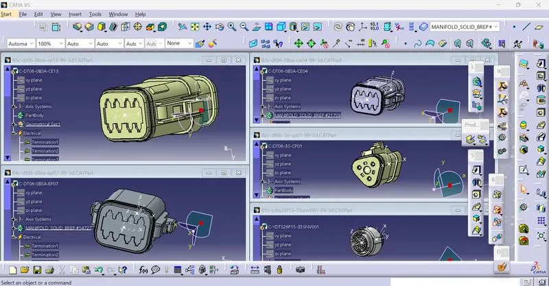
All the connectors of both the harness A and B are downloaded .In part design ,the points and axis are created.In electrical part design,the part is defined as connector.The connector connection point and bundle connection point are defined.The connector is also added to the catalogue.
Connectors in harness A
Connectors in harness B
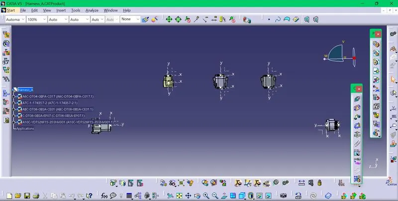
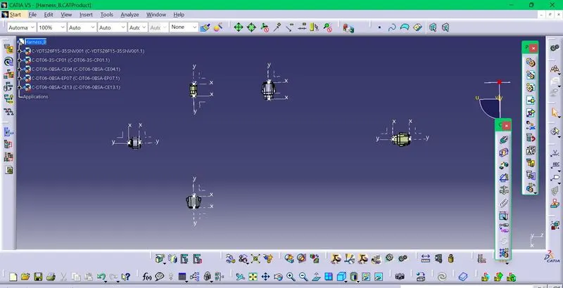
After that,according to the respective harness layout of A and B harness ,the connectors are positioned.Click file,new and product.Go to assembly design,import the connectors according to the layout of the respective harnesses.
After that the connectors are positioned using the compass or manipulation option.
Harness A connector positioning
Harnesss B connector positioning
After positioning ,go to electrical harness assembly,clcik multi branchable option and click the product.
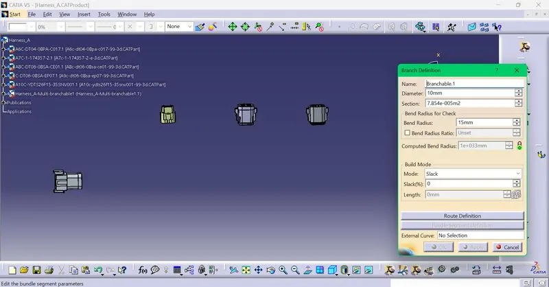
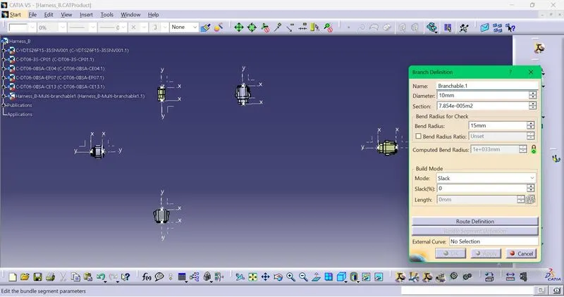
Click branch definition and select the color and diameter of the bundle.The diameter taken is 10mm.
Harness A branch definition
Harness B branch definition
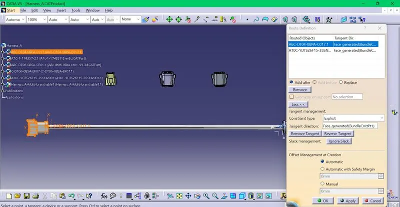
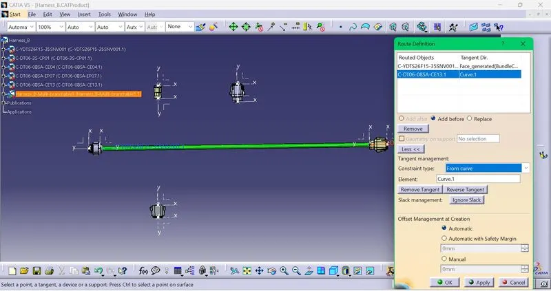
After that ,the route definition is done by selecting the required connectors.
Harness A route definition
Harness B route definition
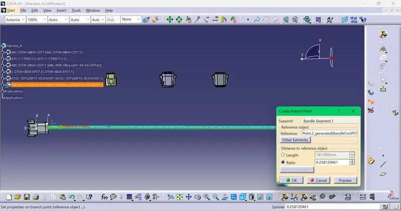
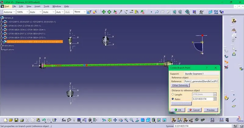
After that,the required branch points are also created using the add branch point option.
Harness A
Harness B
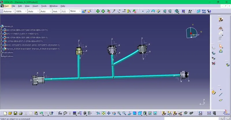
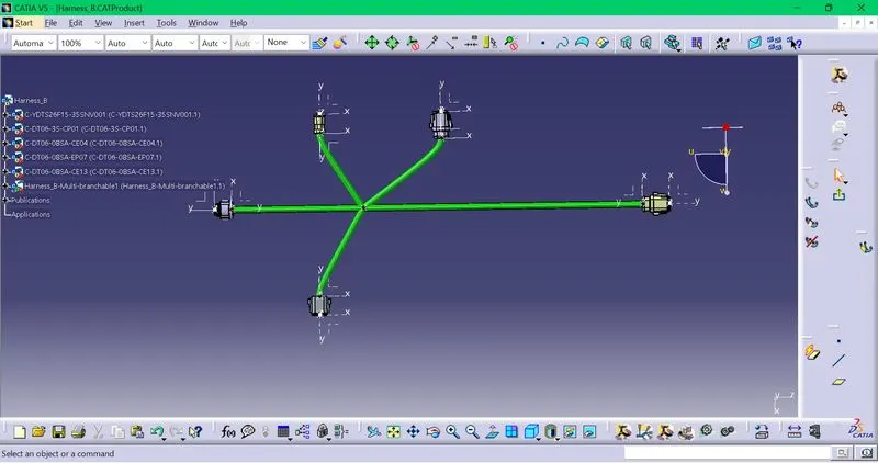
The routing is completed in both the harnesses.
Different color is taken for the harnesses.
Harness A
Harness B
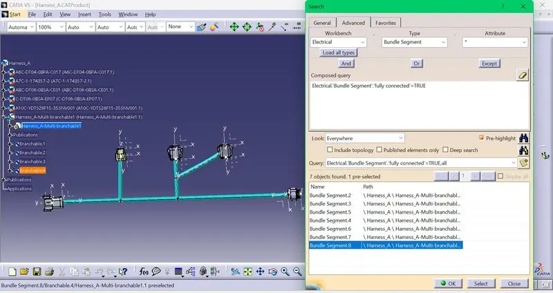
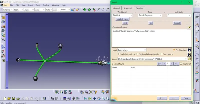
After that,the bundle connectivity is checked for both harnesses.Go to edit,search, on advanced tab,click eletrical in workbench,bundle segment in type and fully connected in attribute from drop down.
In harness A, all the branches created are shown as fully connected.
In harness B,all the branches used are shown as fully connected.
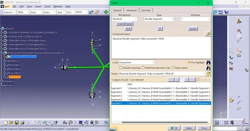
By this,it can be confirmed that there are no disconnected bundle segments.
Now click on file,new and product,go to eletrcal part assembly.Import the harness A and B in this file.Rename the product as Assembly_Harness.
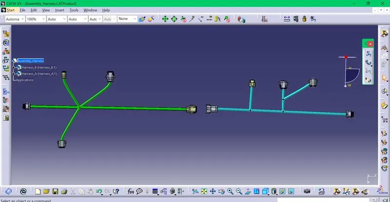
Now using the connect electrical devices option ,make an interconnection between the harness A and B.
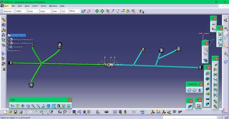
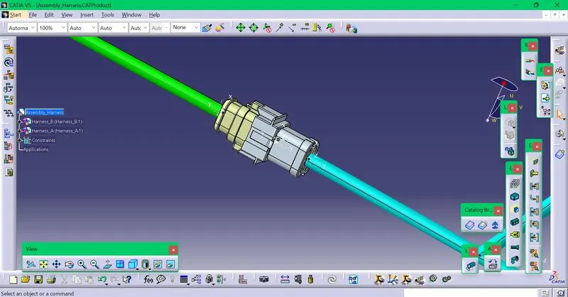
After the interconnection,the bundle connectivity is checked .
On checking ,the condition is set with false to find the disconnected bundle segments.On checking there is no bundle segment found ,which shows that no bundle segment is disconnected.
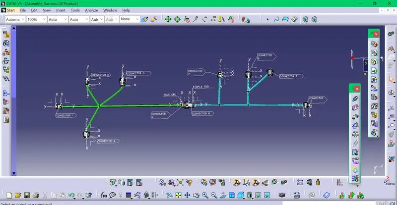
After that,the complete annotation of the connectors is done.
After that ,go to tools click Generate CAT.part option .After the CAT.part is created,the bundles will be grey,so it should be given color again and finally it is saved in the igs format.