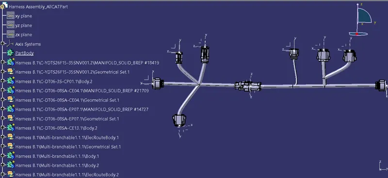
Wiring harness design in CATIA V5 - 3D modeling Week 5 & 6 Challenge
OBJECTIVE
Route the following harness layout in Electrical workbench. Make assumption for harness bundle diameters. Use the connectors provided. After completion of routing,
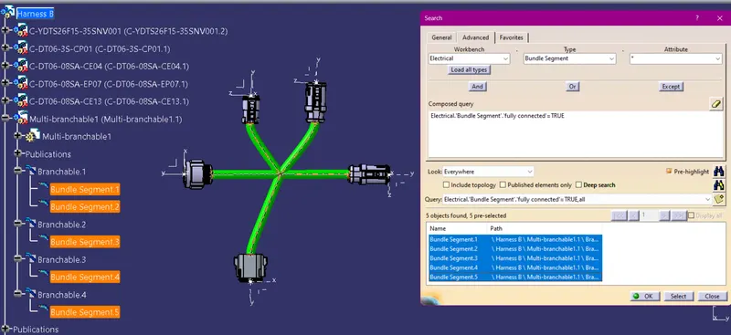
- Check the bundle Continuity. Add snap of result in submission
- Add annotation to all connectors. Make an assumptions for annotations like connect 1 , 2 etc
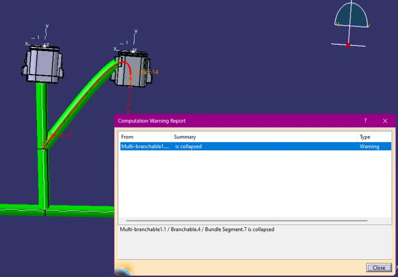
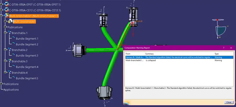
- Check for the bundle warning. Add snap.
Generate CAT.part of harness assembly and convert is in. igs format.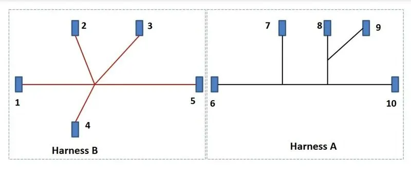
PROCESS
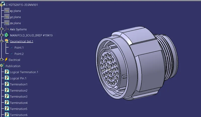
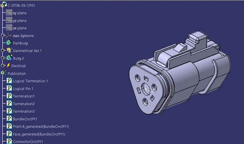
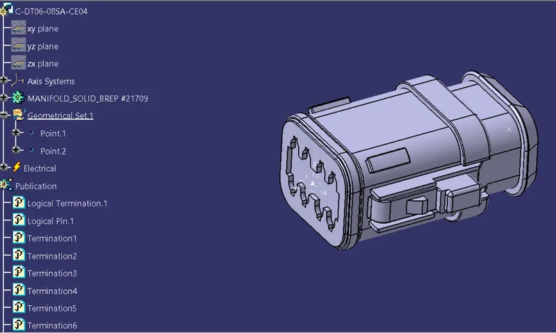
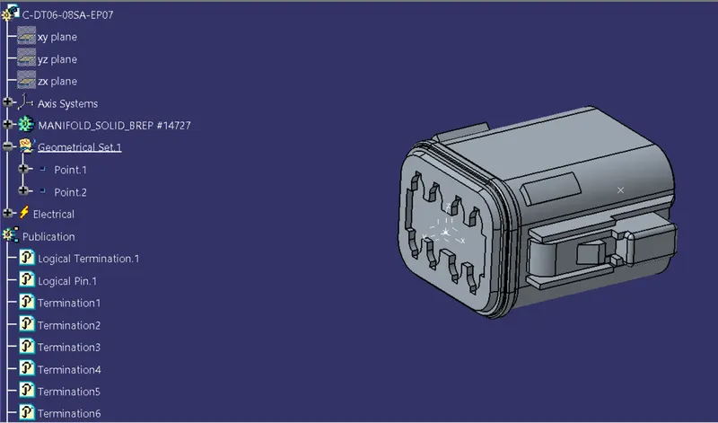
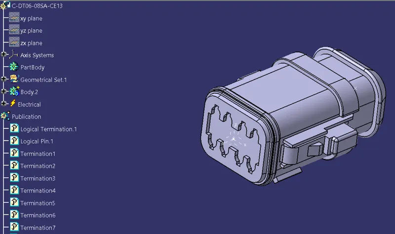
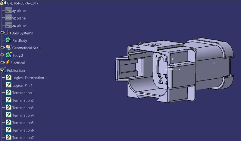
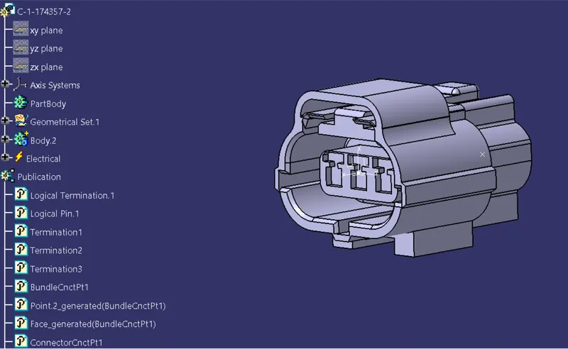
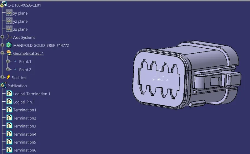
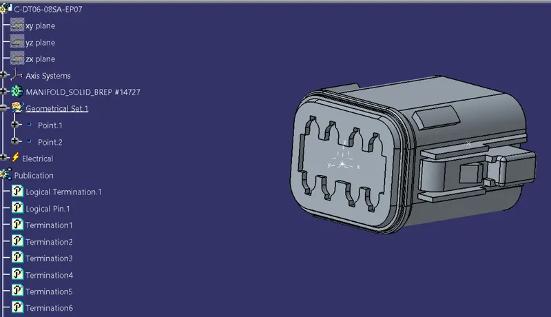
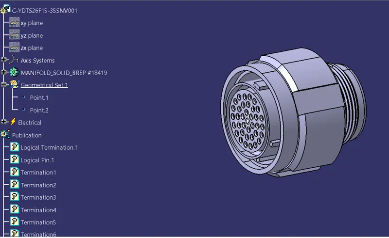
STEP 1- Convert all mechanical connector parts into electrical parts
Define all the electrical connectors geometrically and electrically so that they can be used in the wiring harness.
STEP - 2- Create Harnes A and Harness B
- Create 2 New product file Named Harness A and Harness B
- Arrange all the connector according to the Instruction in the Electrical Harness Assembly
- Route all the connectors using Multi Branchable Document command.
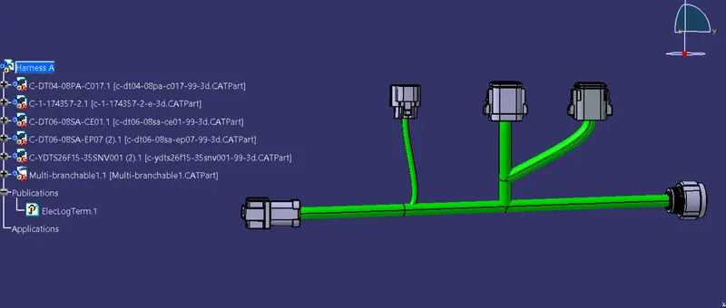
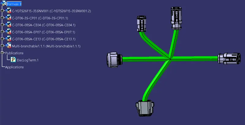
STEP - 3- Create Harness Assembly
- Copy Harness A & Harness B into a new product file
- Connect those two Harness By using Connect Electrical Devices command
- Provide 3D annotation to all the connector
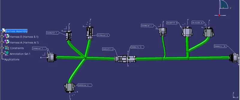
STEP - 4- Check Bundle Continuity
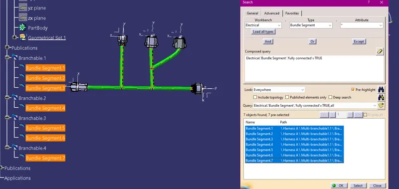
STEP - 5- Check for the bundle warning
STEP - 6 - Generate CAT.part of harness assembly and convert is in. igs format.