Wiring harness design in CATIA V5 - 3D modeling Week 5 & 6 Challenge
Report On Wireharness design by creting the interconnection between two harnesses.
Aim: To create harness A and B as seperate product then interconnecting them together in one product file to create the one harness.
Given:
Link for CAD data and routing map data:
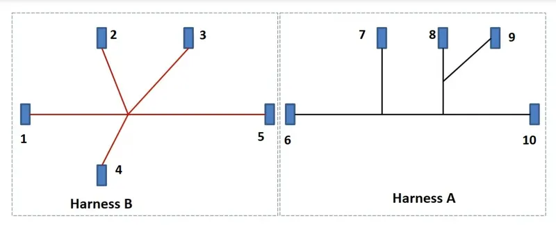
Step 1: Download all the data such as connectors step/igs file from the given link and open the Catia V5 to define them electrically.
- Open each connector file seprately define them electrically by first creating the Geometrical parameters. then define the part as connector and then define the connector connection point and bundle connection point and define the cavity connection point in the connector if it is present in the connector.
- Now create catlog file for harness A and B connectors and add the resprctive connector into their familes such that there is one male part connector on harness A and one female part of the same spec connector on harness B so that we can interconnect them on later stages.
Step 2: Now create seprate product file for harness A and harness B, start working on harness A product file by clicking on geometrical bundle on electrical assembly workbench.
- Now add the connectors required in harness A from the catalog created in previous stage, and position each connector acc. to the given layout for harness A in the mechanical Assembly workbench.
- Now to create routing we first create the layout in the sketcher workbench as shown below:
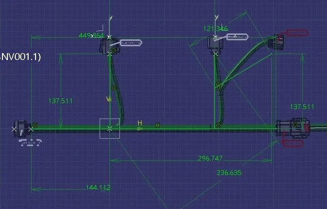
- Then we postion each connector on the each end point of sketch by using the commands such as manipulation, compass movement in the mechanical assembly workbench.
- Now create routing between these connectors by using the command multibranching in the electrical harness assembly workbench. Give the daimeter of main branch to be 15mm and bed radius ratio to be 1.5, select the routing objects as end point on the connectors and create the branches as per layout.
- During routings we faced the problem/warnings as shown below:
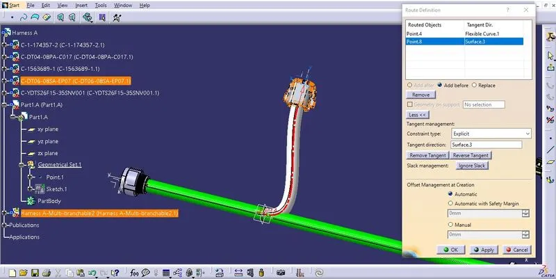 , by reversing the tangent direction for the routing point we solved this problem.
- We got one warning as shown below:
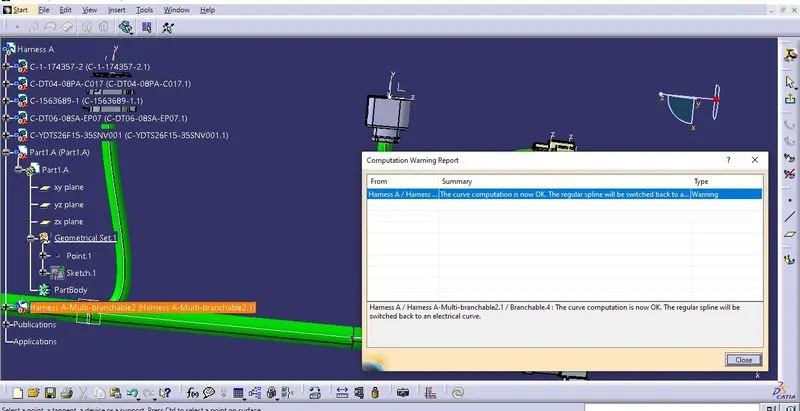 , we solved this issue by changing the computed bend radius such that it exceed the bend radius by position of sub branch point in branch.
- Now on checking the continuity of the harness we open search in edit option of workbench then selected the advance and choosen the workbench as electrical, type as bundle segment and attribute as fully connected then applied false then we got this result:
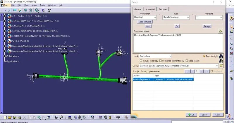 , we solved this issue by creating the branch again, and we got the final result as shown below:
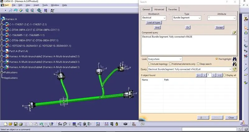 , it means that harness A is continuous.
Step3: Now crete product file naming it as harness B and follow the same procedure as we did for harness A.
- During routing we face the following problems as shown below:
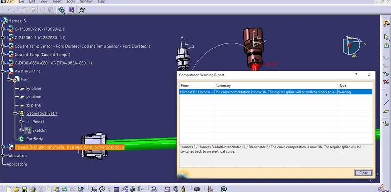 , we solved this issue by selecting the seprate routing for that branch.
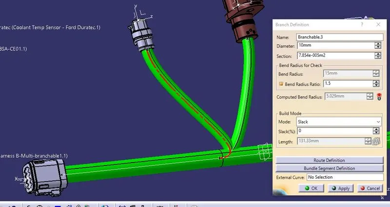 , we face another issue in this branch that our computed radius is less than bend radius so we reverse the direction of tangent then we resolved this issue.
- In the checking for continuity result for harness B we got the following result:
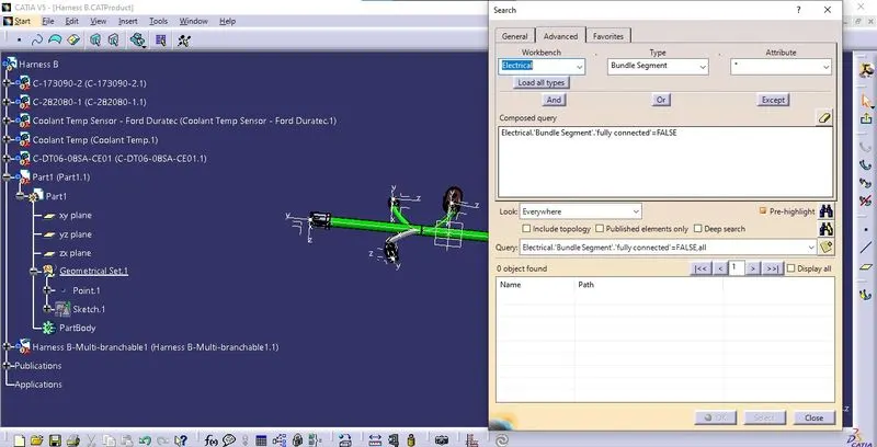
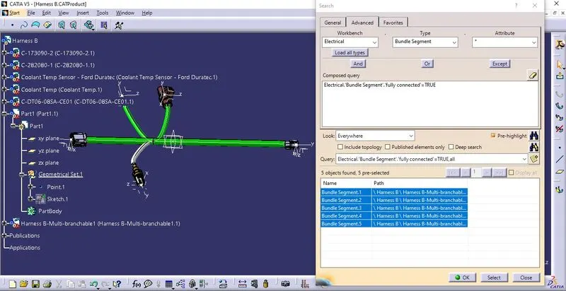 , it means that our harness is continuous.
Step 4: Now create a new product file and add harness A and B in that part file use the command such as manipulation, move by compass in the mechanical assembly workbench to bring the male part connector in harness A and female part in connector B to join both together so we get the following result:
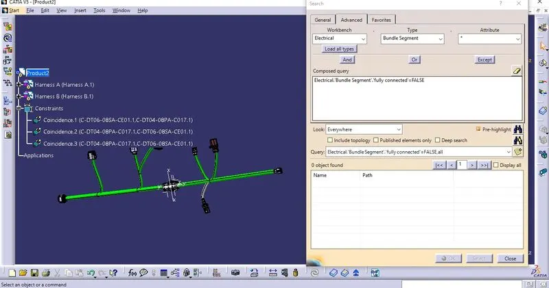 , it means that it is continuous also.
Step 5: We add the desired annotations to every connector by selecting the view front reference to select the view and add flag note command to add the annotations at the desired location. which is as shown below:
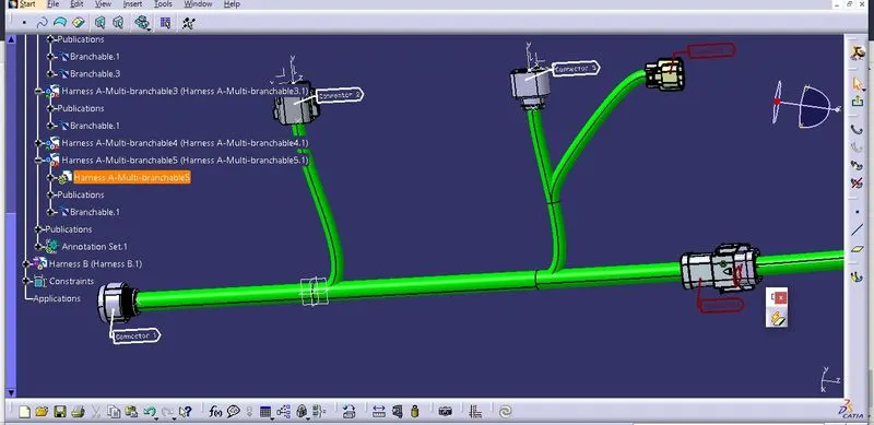
Step 6: Now we convert this product file into CATpart file by using the command CATpart from product in the mechanical assembly design workbench in tools option and we can save this .catpart file into .igs file.