Wiring harness design in CATIA V5 - 3D modeling Week 5 & 6 Challenge
OBJECTIVE:
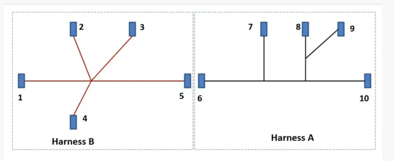
- To Route the following harness layout in the Electrical workbench.
- Add protective covering on all branches.
REQUIREMENTS:
- CATIA V5.
- Knowlege of using CATIA V5.
GIVEN
CAD data of the following
Harness A and it's sub parts.
Harness B and it's sub parts.
LAYOUT DIAGRAM
HARNESS B PROCEDURE
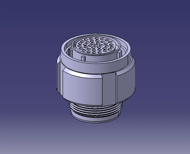
Harness B Component 1
PROCEDURE
The following was defined for all the connectors:
- Connector connection point.
- bundle connection point.
- axis system at the connector connection point.
- define all the connectors as electrical components.
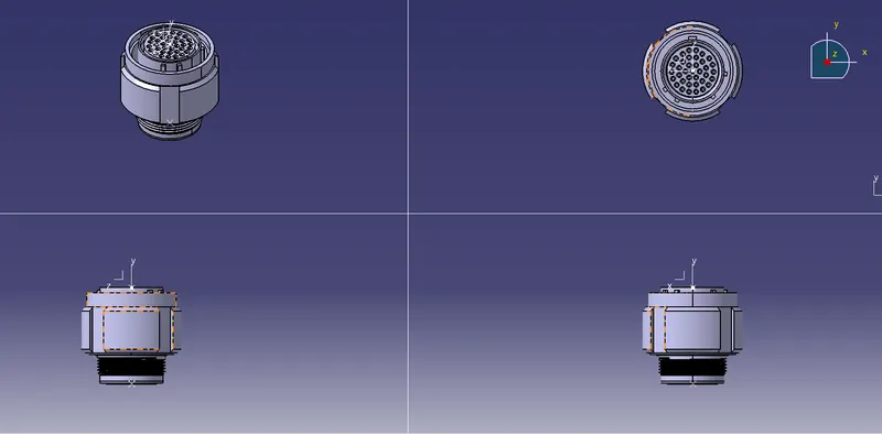
ORIENTATION VIEWS
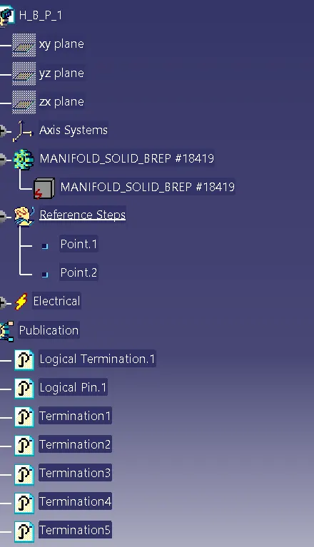
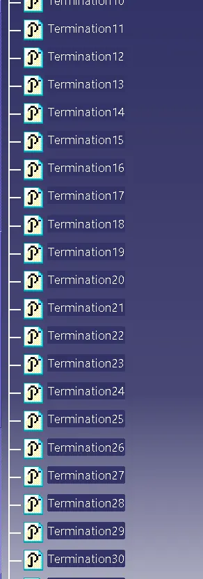
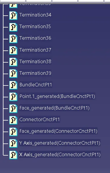
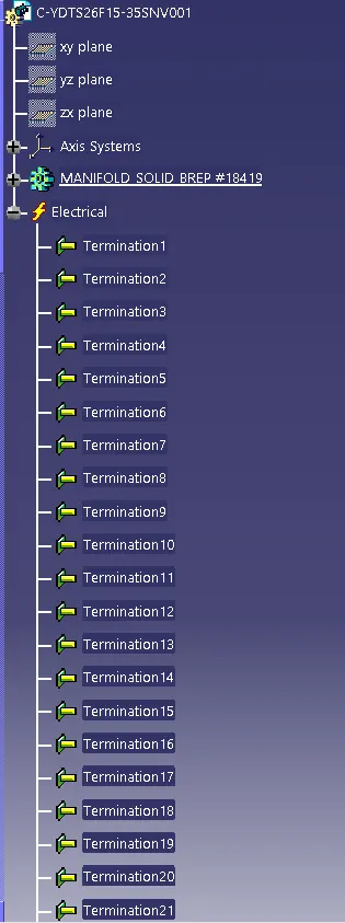
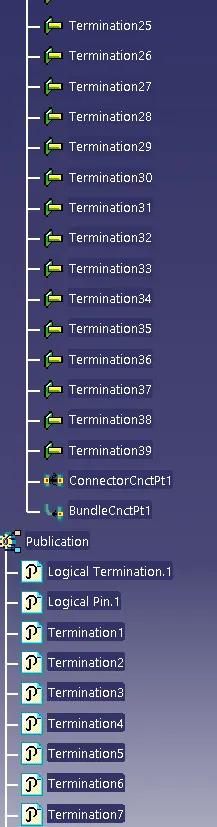
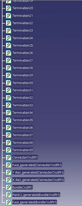
FEATURE TREE
Harness B Component 2
PROCEDURE
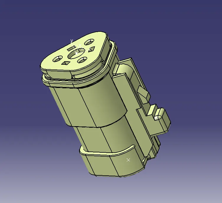
The following was defined for all the connectors:
- Connector connection point.
- bundle connection point.
- axis system at the connector connection point.
- define all the connectors as electrical components.
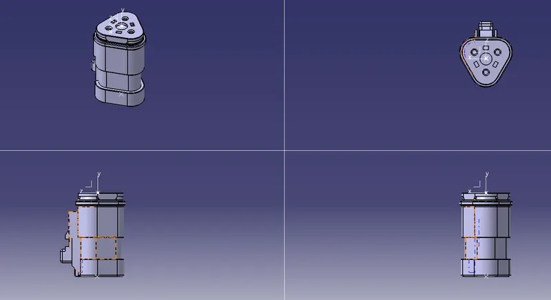
ORIENTATION VIEWS
FEATURE TREE
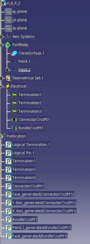
Harness B Component 3
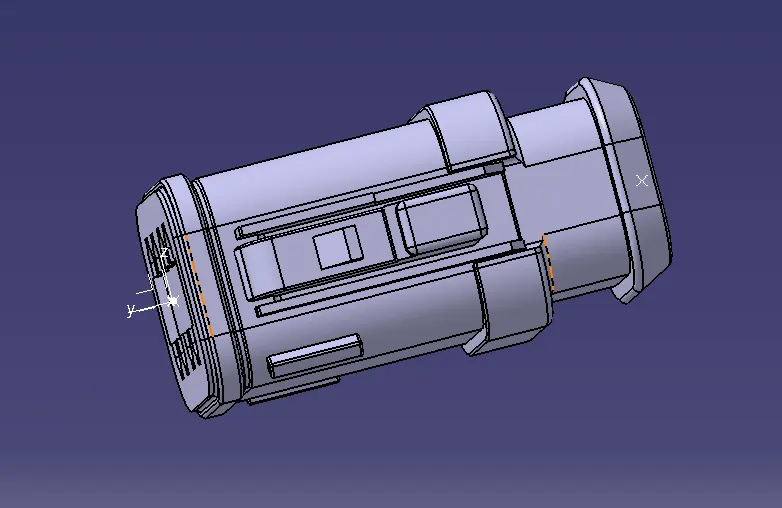
PROCEDURE
The following was defined for all the connectors:
- Connector connection point.
- bundle connection point.
- axis system at the connector connection point.
- define all the connectors as electrical components.
ORIENTATION VIEWS
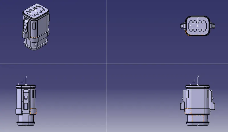
FEATURE TREE
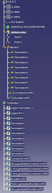
Harness B Component 4
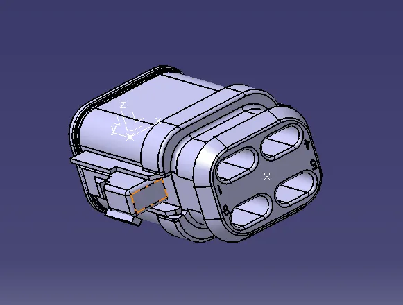
PROCEDURE
The following was defined for all the connectors:
- Connector connection point.
- bundle connection point.
- axis system at the connector connection point.
- define all the connectors as electrical components.
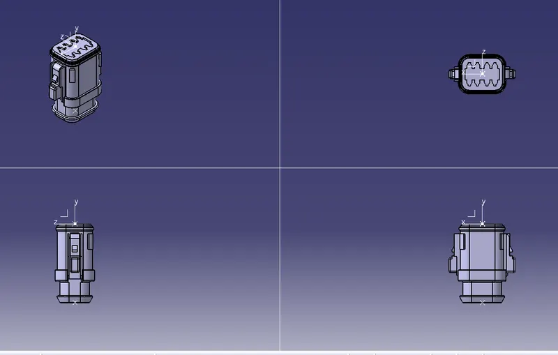
ORIENTATION VIEWS
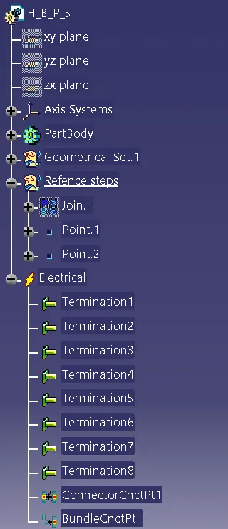
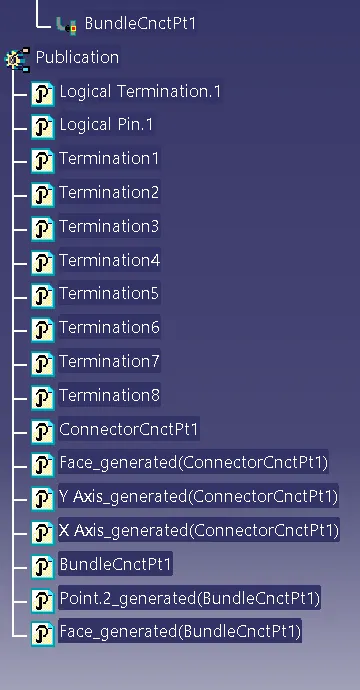
FEATURE TREE
HARNESS A PROCEDURE
Harness A Component 1
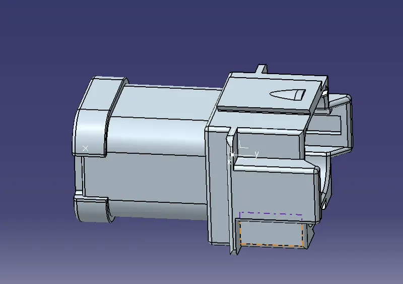
PROCEDURE
The following was defined for all the connectors:
- Connector connection point.
- bundle connection point.
- axis system at the connector connection point.
- define all the connectors as electrical components.
ORIENTATION VIEWS
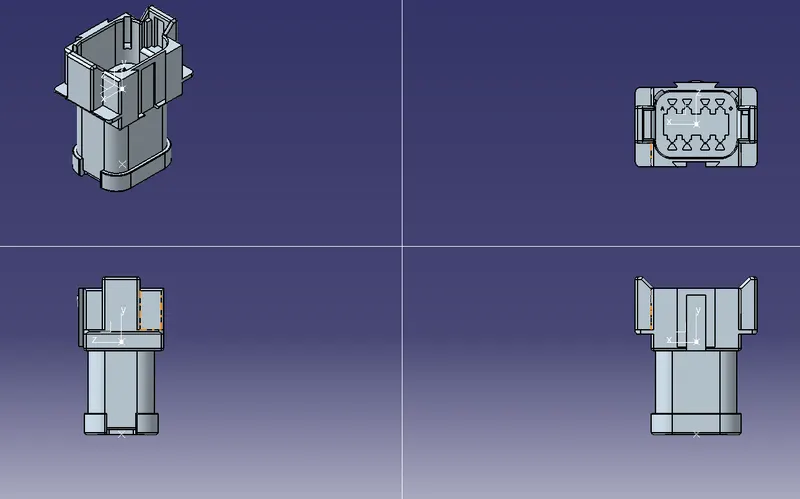
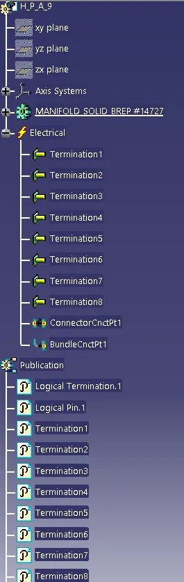
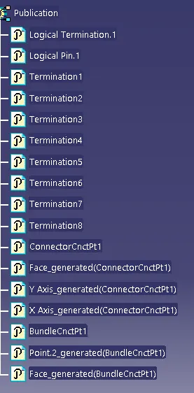
FEATURE TREE
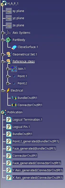
Harness A Component 2
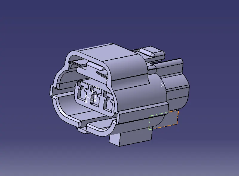
PROCEDURE
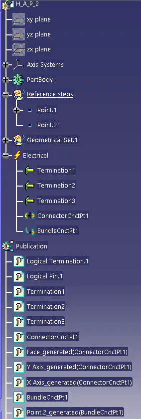
The following was defined for all the connectors:
- Connector connection point.
- bundle connection point.
- axis system at the connector connection point.
- define all the connectors as electrical components.
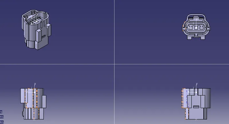
ORIENTATION VIEWS
FEATURE TREE
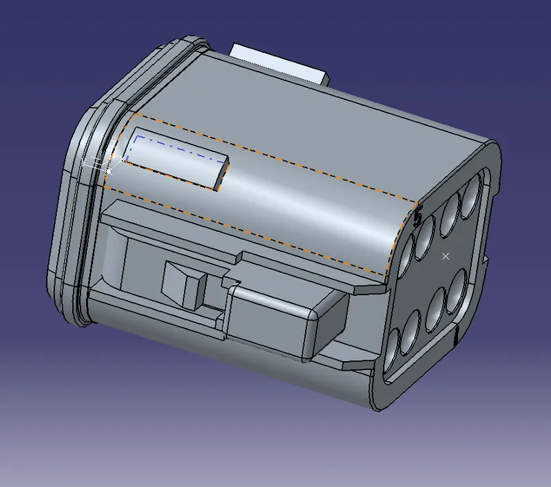
Harness A Component 3
PROCEDURE
The following was defined for all the connectors:
- Connector connection point.
- bundle connection point.
- axis system at the connector connection point.
- define all the connectors as electrical components.
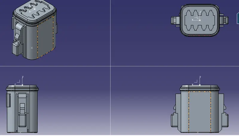
ORIENTATION VIEWS
FEATURE TREE
Harness A Component 4
PROCEDURE
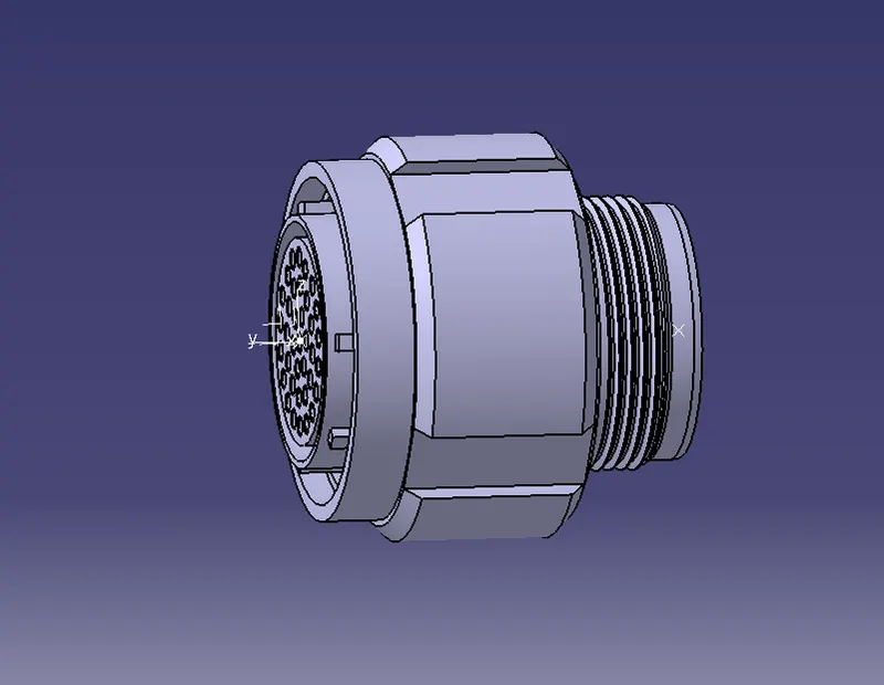
The following was defined for all the connectors:
- Connector connection point.
- bundle connection point.
- axis system at the connector connection point.
- define all the connectors as electrical components.
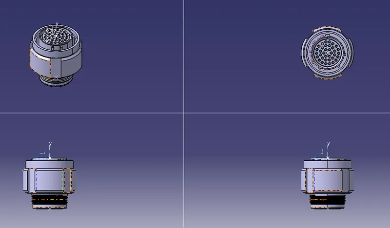
ORIENTATION VIEWS
FEATURE TREE
HARNESS B ASSEMBLY
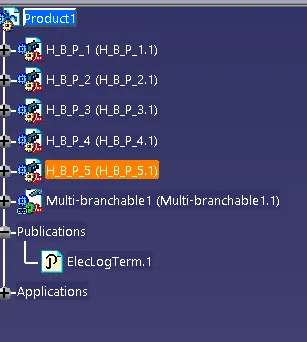
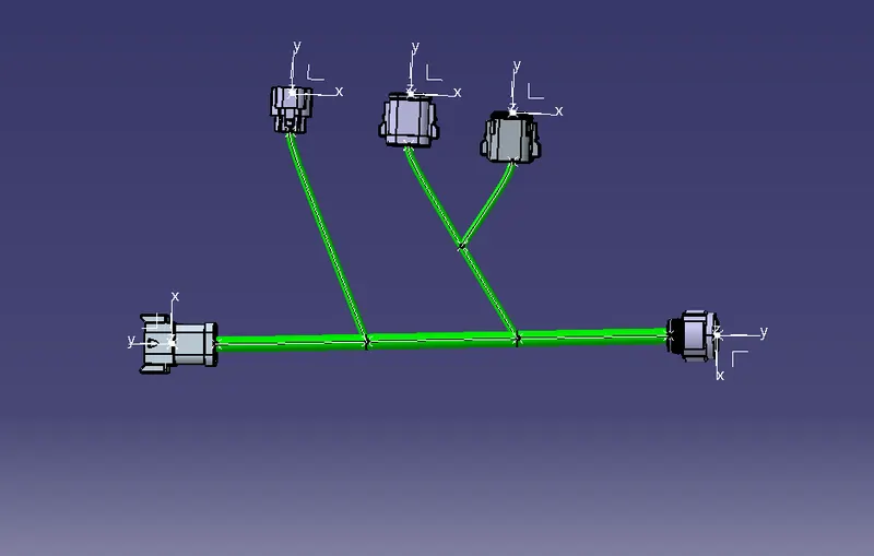
After all the connectors are defined, the workbench was switched to Electrical Harness Assembly where Geometrical Bundle was activated. All the connectors were routed using the Multi-Branchable Document command.
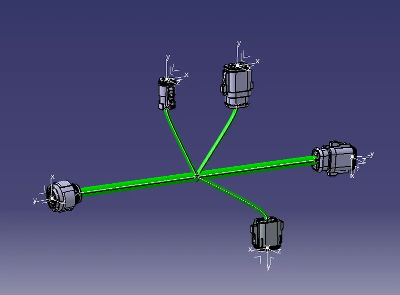
FEATURE TREE
HARNESS A ASSEMBLY
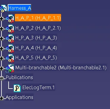
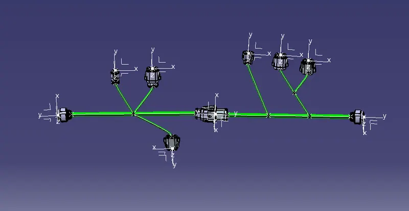
After all the connectors are defined, the workbench was switched to Electrical Harness Assembly where Geometrical Bundle was activated. All the connectors were routed using the Multi-Branchable Document command.
FEATURE TREE
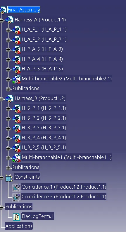
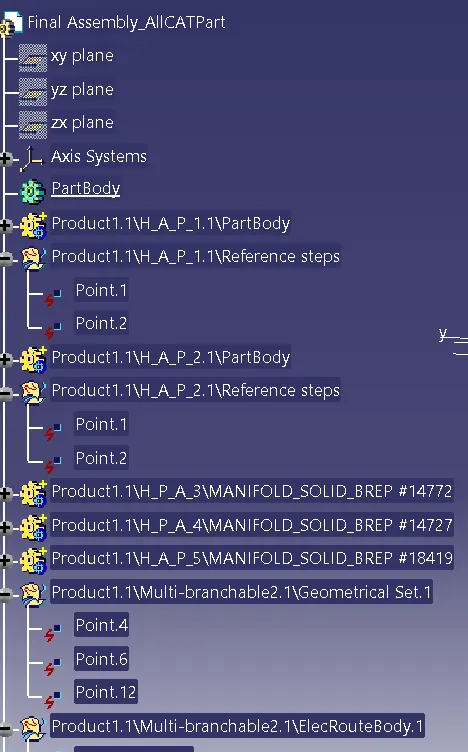
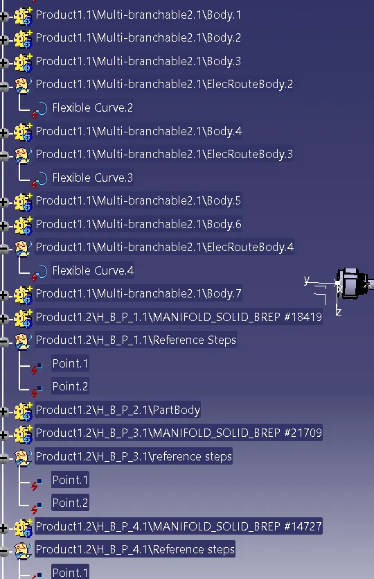
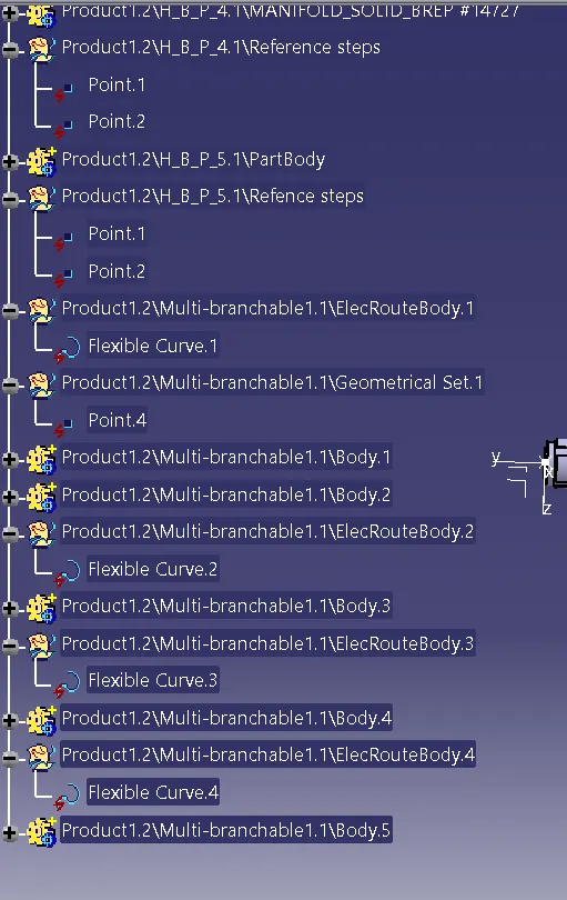
FINAL ASSEMBLY HARNESS
FEATURE TREE
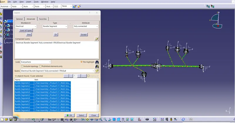
CONNECTIVITY CHECK
Go to Edit, select Search a table appears, click on advance tab.
Under that select Bundle Segment under Type.
Select Fully connected under attribute.
Click on search button below.
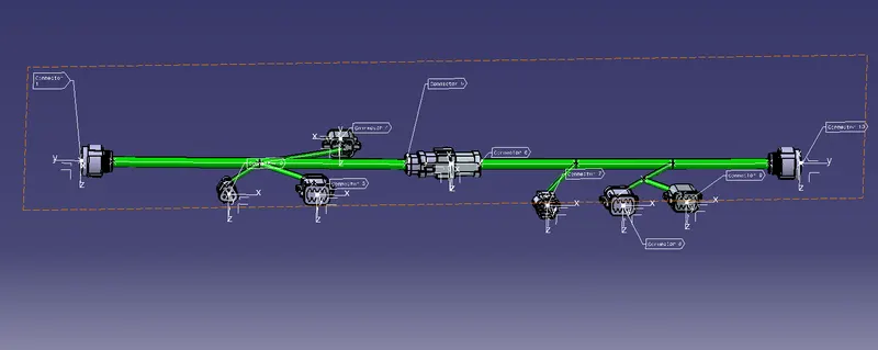
ANNOTATIONS
Switch the Part Assembly and Use annotations to name them.
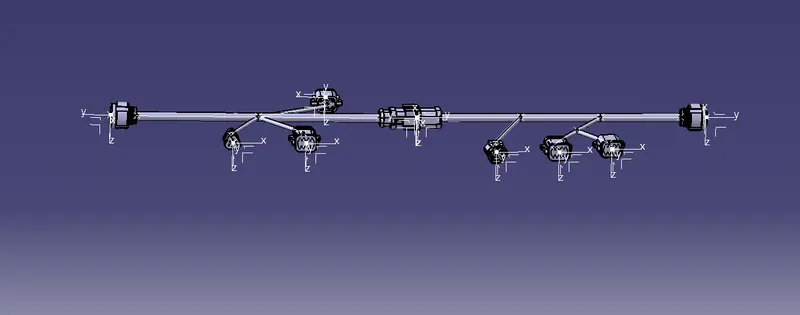
Converted as a part body and save as IGS Format
FEATURE TREE
CONCLUSION
- The Points and Axis system were created to each and every component and converted into electrical components.
- The Harness A Assembly and Harness B Assembly were created respectively by its components.
- Both the Harness were used to create final assembly.
- Annotations were given to each component and named it accordingly.
- The whole bundle connections were checked usign search option to check the experiment connections.