Wiring harness design in CATIA V5 - 3D modeling Week 5 & 6 Challenge
Aim :
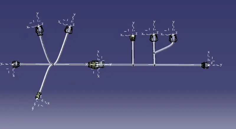
Route the Wiring harness layout in Electrical Workbench with given connectors according to the given instructions from the image below
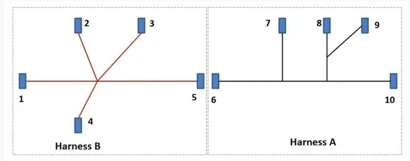
- After routing, Check the bundle continuity.
- Add annotations to all the connectors with given numbering.
- If bundle warnings arise, resolve them as per instructions.
- Generate CAT.part of harness assembly and convert it to igs format.
Methodology
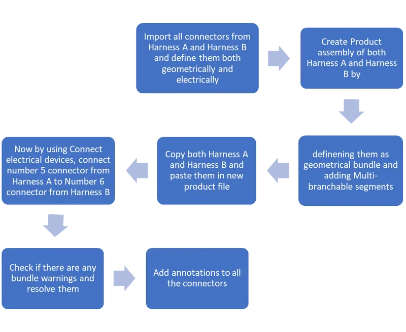
Procedure:
- First Download and import all the connectors from Harness A and Harness B in Catia.
- Define them geometrically and electrically as connectors and define bundle connection point, connector connection point
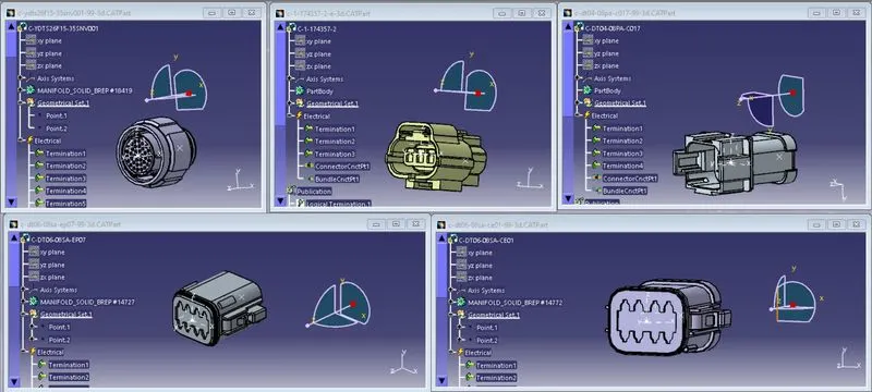
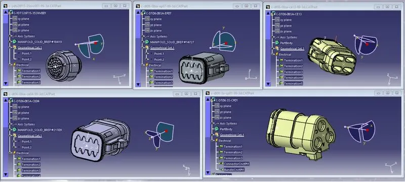
- Now import all the connectors of harness A and harness B in two seperate product files and arrange them as per instructions with help of snap, smart move and manipulation
- Open Electrical Harness Assembly and define them as geometrical bundles, Next by using Multi-branchable create bundle segments as per instructions
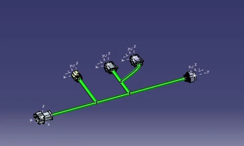
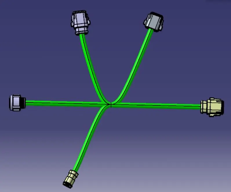
- Copy both the product files of Harness A and Harness B . After that create new product file, in that paste both of these under the product
- Arrange both of them in such way that they dont clash with each other by using manipulation
- Then open Electrical Harness Assembly and by using Connect electrical devices command, connect connector 5 and 6 and click update.
- If there are any bundle segments errors, resolve them. But in this case there were no errors so proceed further.
- After this step check for bundle segments connection- whether it is fully connected or not.
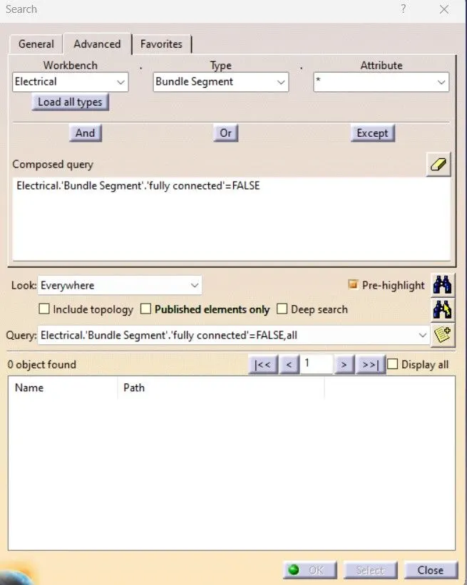
- From this we can see that all the bundle segments are fully connected
- Next step is to create annotations
- For this first we have to select a plane for annotations representations, so i have selected a face on the connecter as its plane of representation
- Next add flag note with ledger annotations to all the connectors with numbers
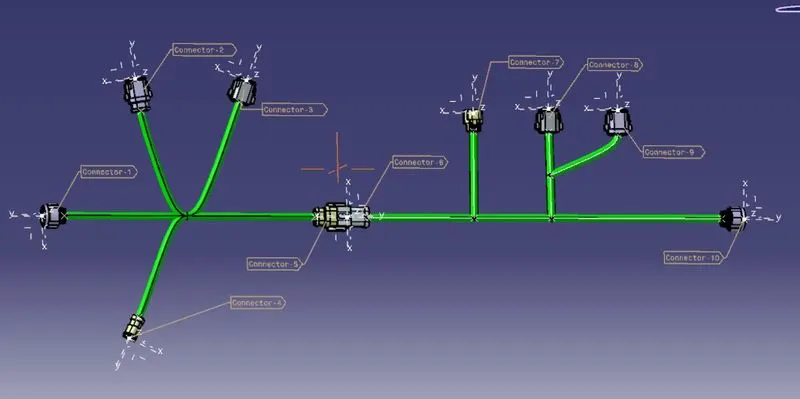
- Next step is to create a catpart from product file and save as igs file
- For this we have to select generate CAT part from product from tools in assembl workbench na dselect the product
- So after creating the CATpart, while saving click save as and select igs type in file format and save
- With this we have igs file of the assembly
Conclusion:
- Routing of the harness assembly of both Harness A and Harness B is completed.
- Connected both Harness A and Harness B in new product file with Connect electrical device command
- Checked for bundle segments errors and connectivity of bundle segments
- Added Annotations to all the connecters
- Created IGS file of the CATpart of the product file.