Advanced Sheet Metal Design Using NX Cad Challenge_1_Casing Design
Design of Casing by using Siemens NX Sheet Metal Application
Objective :
The objective of this challenge is to design a Sheetmetal Casing with the given instructiona to get a desired output and to know more about the tools used in the challenge.
Introduction :
First, What is sheet metal ?
Sheet metal is comprehensive cold working process for metal sheets(usually below 6mm), including shearing, punching/cutting, folding, riveting, splicing, forming(such as car body) etc. Its remarkable feature is the same thicknessof the same part.
Basically it is one of the shapes and forms metals can be bought in. #(only between 0.5 to 6mm)#
NX Cad Sheet metal Application :
Creating fast, accurate flat patterns is the goal of any organization that manufactures products which contain sheet metal parts. NX Sheet Metal provides a set of tools within the NX design environment that allows for simple and fast design of sheet metal parts, dependent on their material and manufacturing process.
Its Advanced Sheet Metal features—Advanced Flange, for example—are targeted at parts that have non-linear bend lines and are typically not manufactured with straight brake tooling. This allows more automotive parts to be created and flattened using the NX Sheet Metal (Advanced) application, typically in automotive parts around the curved edges of a plate that requires a strengthening flange. Advanced flanges can be created on non-linear edges or tangent curves. The flanges can follow a contour curved or b-surface face as well as a reference surface, supporting bend allowance and compensation adjustments
This Challenge of designing a casing is done by using Sheet Metal Application of Siemens NX 12 Software.
Here in this challenge, I have used various tools given by the NX design environment such as tab, flanges, beads, Normal cutout, Mirror feature, bend, braking corners, sketch tools, bend, rebend and etc.
Design Methodology :
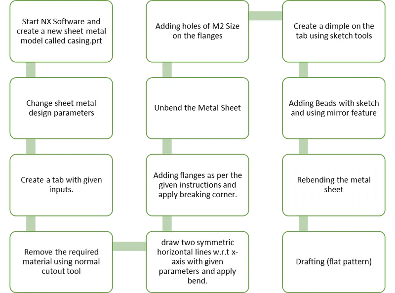
The design process of the Sheetmetal Casing is done as per the flow chart.
Description :
All the tools used while doing this challenge are as follows,
Sketch : command to create a sketch and define its sketch plane, orientation, or origin. You can create a sketch on an edge, curve or planar face. After you create a sketch, you can modify its placement with the Reattach Sketch command.
Tab : Use the Tab command to create a base feature or a tab by extruding a sketch along a vector by a specified thickness value. You can also use this command to create a secondary tab if the work part includes existing sheet metal features. You can do this by adding material to existing faces and bend regions of an existing sheet metal part.
Normal Cutout :to cut material by projecting a sketch onto the model and then cutting perpendicular to the faces intersected by the projection. You can use planar sketches or 3D curves to specify the section for the normal cutout. If the sheet metal part has multiple bodies, you can specify the target body on which you want to create the normal cutout.
Bend : modifies the model by bending material on one side of a sketch line adding a bend between two sides.
Flange : Adds a flange to an angle to a planar facce and adds a bend between the two.
Breaking Corners : Use the Break Corner command to round or chamfer sharp corners of a tab or flange. When you create blends on thick edges, to save design time, you can filter out invalid edges.
Unbend : to unbend a portion of the part to construct cutout features, hole features, or deform features across a bend, we use unbend command.
Hole : this feature helps in creating hole on the sheet metal as the name suggest, with respect to given inputs.
Dimple :Use the Dimple command to lift an area of the model inside a sketch that simulates a stamping tool. You can create an indentation in a sheet metal part using a sketched section as the dimple outline. Like the Drawn Cutout command, the Dimple command makes an indentation in the sheet metal part, using a sketched... as its outline. The difference between the two is that a Dimple feature has a bottom face whereas a Drawn Cutout feature does not.
Beads :Use the Bead command to lift material along the contour of a sketch that simulates a stamping tool. Beads can also be created to stiffen sheet metal parts
Mirror Feature :to mirror one or more selected features about a selected datum plane or planar face we use mirror feature.
Rebend : Use the Rebend command to return an unbend feature to its previous bent state. Any features added after the unbend operation are properly repositioned during the rebend operation.
Flat Pattern :
Use the Flat Pattern command to create a 2D representation of the flattened 3D sheet metal part.
You can:
-
Create a flat pattern from a formed sheet metal body or from flat solids.
-
Control orientation of the Flat Pattern view for the upward face having non-linear edges. To do this, you need to specify a CSYS while defining the orientation.
-
Represent holes smaller than or equal to a specified diameter value as centermarks in the flat pattern view. This is useful when holes need a different manufacturing process.
-
Create an associative flat pattern fixed at the current timestamp. This helps you create a flat pattern view at the intermediate stage of the part design.
-
Edit the bend properties, such as bend sequence and bend names, using the Bend List command after making the Flat Pattern view as the active view
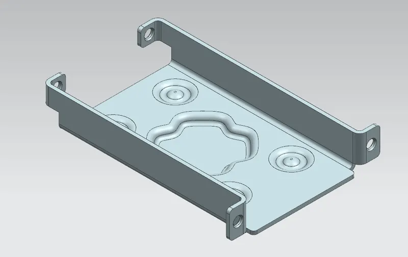
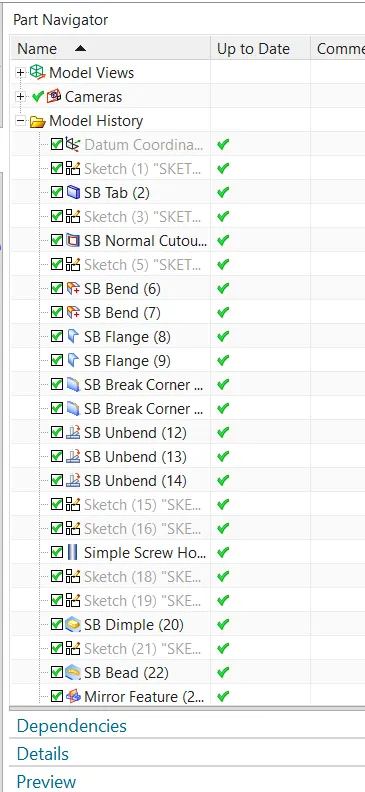
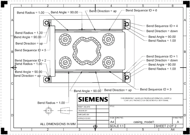
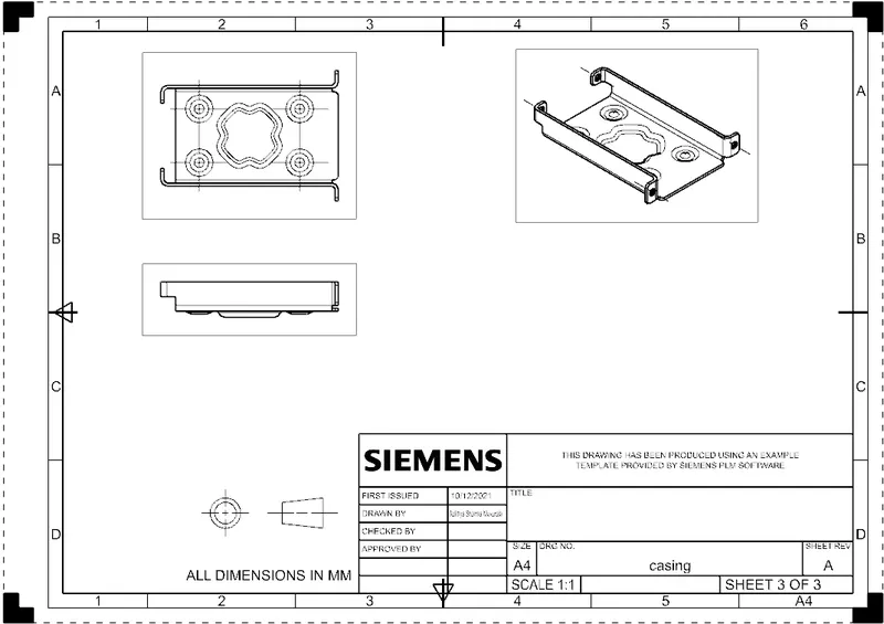
First, I've set the preference of the sheet metal then created a tab of 1mm thickness. Then I removed some of the portion of the tab by using normal cutout .Made a sketch of two symmetric horizontal lines w.r.t to x-axis in XY plane and used them to do bend on the tab. I added flanges to the bends and used the break corner command to round the edges.After unbending the shee metal, I added holes, dimple by using a sketch and beads to the sheet metal and re-bended the sheet metal. After completing the design of the casing as per the given inputs I've done flat pattern of the casing which may not appear. to make it visible double click on the flat pattern in the part navigator. Then I made a drafting file of A4 size and add a new base view. In the base view dialogue box, i've selected in the option model view to use FLAT PATTERN#1 so that we can view the flat pattern. I added another drafting file of A4 size with different view of the casing (top,front,isometric) by using view creation wizard and saved the file.
Images :
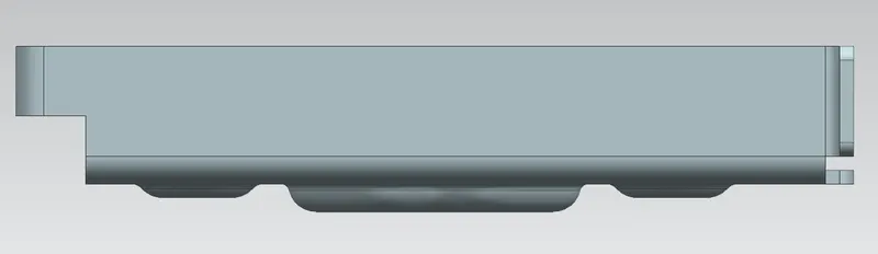
Front View -
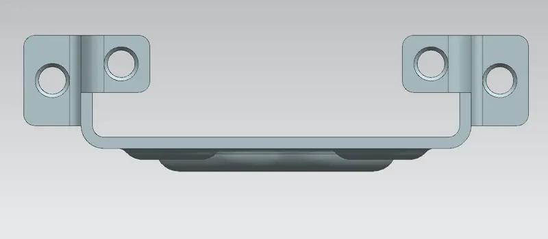
Side view -
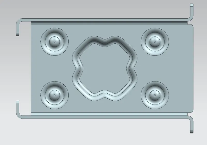
Top view -
Isometric view -
Part navigator -
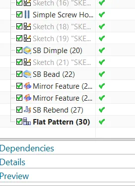
Drawing sheet images -
Conclusion :
By doing this challenge of design of Sheet metal Casing, I've learnt about various tools like tab, flange, bend, holes, beads, dimple and many more from the Sheet metal Application of NX.I also learned about Drafting in NX.