Advanced Sheet Metal Design Using NX Cad Challenge_2_Box Assembly
Advance Sheet Metal Design Using Siemens NX_Box Assembly
Objective :
The objective of this challenge is to design a Box Assembly by using Siemens NX Sheet metal Application and try to understand the tools used in this challenge.
Introduction :
Metal enclosure boxes serve a variety of purposes. From items such as lockboxes to filing cabinets, to more technical and ubiquitous uses such as electronics enclosures, you can find metal enclosure boxes just about anywhere. Depending on the use, the design of the item, and even the aesthetic, whatever use you have in mind for an enclosure box, there is a sheet metal out there that will work best for its fabrication. Sheet metal is cut, stamped, punched, sheared, formed, bent, welded, rolled, riveted, drilled, tapped, and machined. Hardware can be inserted into sheet metal components. The components can be brushed, plated, anodized, powder coated, spray painted, silk screened, or otherwise marked. And, of course, parts can be riveted, screwed, or welded into complex assemblies.
Now in this challenge we will try to design a Sheet metal box assembly.
Design methodology :
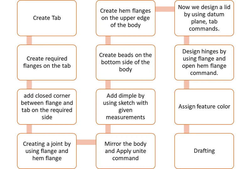
below flow chart will describe the work flow of design of box assembly.
Description :
All the tools and process used while designing the box assembly are as follows
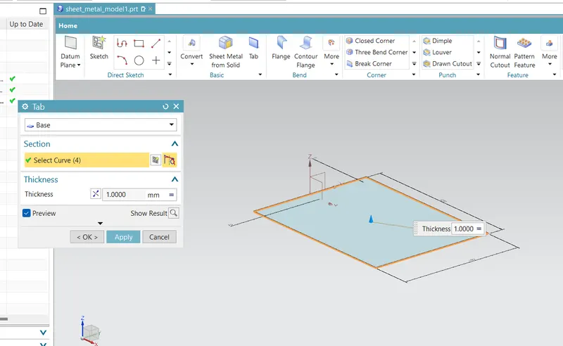
- tab : first, we select the tab tool and select XY plane to sketch a curve on the plane for the tab.Here we will draw a rectangle of 200×150mm and finish the sketch to create the tab.
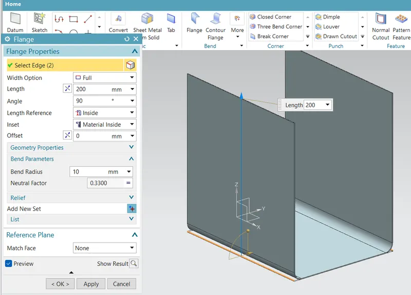
- Flange : it is used to create an extended part(bend) of a sheet metal. here we use normal flange of 200mm with a bend radius of 10mm on the selected edges. The length reference is given as inside and inset is selected as material inside.
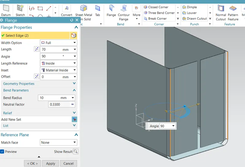
then we use flange on the other selected edges with 70mm length.
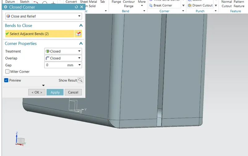
- Closed corner : closes a corner where two adjacent flanges meet by extending the bends and flanges. here we select two adjacent bends with close and relief option and apply closed corner.
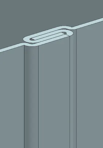
Flanges with hem flanges : We already know what a flange is so here we will discuss about what hem flange is and how these flange and hem flange are used below. Hem flange command modifies the model by folding the edge of a sheet metal flange over onto itself for the purpose of safe handling or to increase edge stiffness.
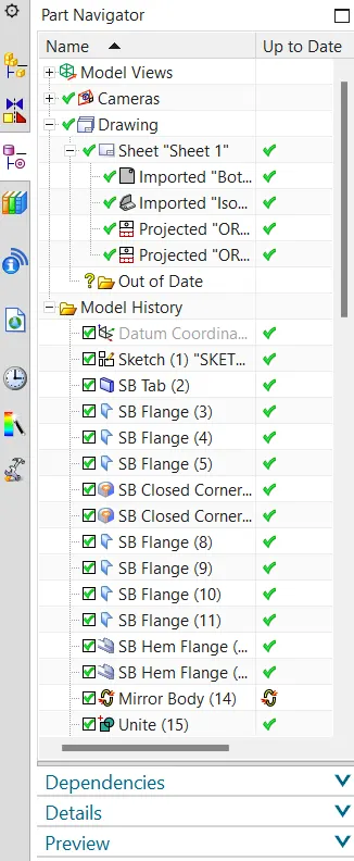
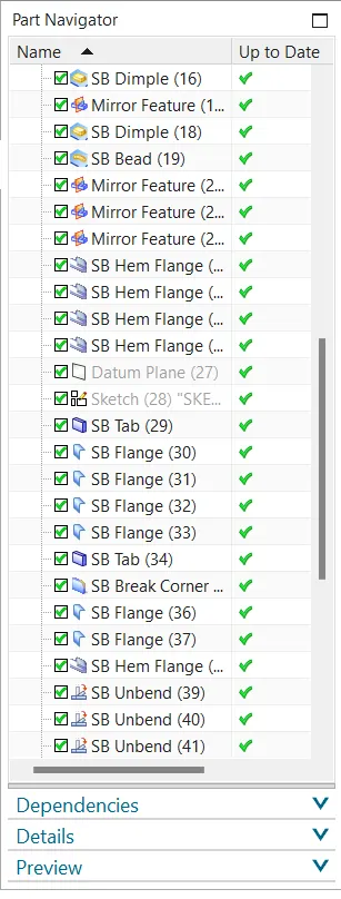
Here First we will do flange with given dimensions on SB flange 4 as per part navigator, then add another flange on flange that was done before with given dimensions and do a open hem flange. Then we do the same on the SB flange 5.
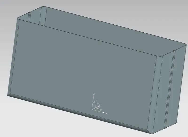
Mirror body : This command is as simple as it sounds. It just copies a body and mirrors it across a plane. Now here we select the whole body and select the YZ plane to mirror the body
Unite : This command combines the volume of two or more solid bodies into a single body. Here we select the body and mirrored body and apply unite command.
Dimple : It just lifts an area of the model inside a sketch that simulates a stamping tool. here by using a sketch we create a dimple and use mirror feature to mirror on the other side by selecting XZ plane as reference.
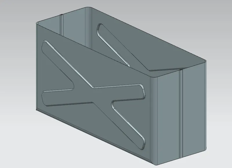
After creating the x shaped dimple, we create another dimple by using sketch as reference on the bottom of the body.
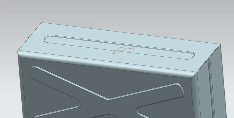
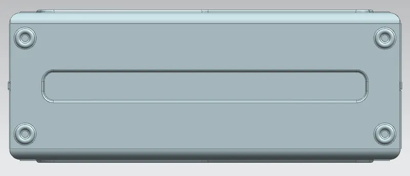
bead :this command is used to lift material along the contour of a sketch that simulates a stamping tool. here we create a bead of depth 2mm and radius 2mm. And then we do mirror feature to the bead to make the rest of the beads on each end of the base.
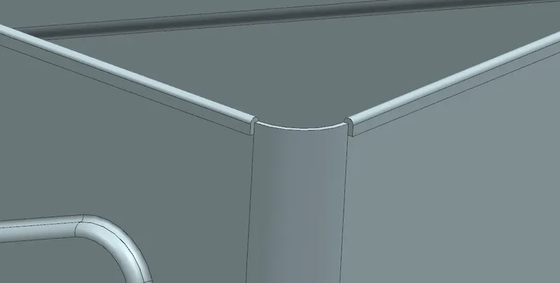
Now, we create Closed hem flanges on the upper edges with fange length of 2mm and inset as bend outside
Design of lid with hinges
Datum plane : Creates a datum plane used to construct other features. here we construct a datum plane with 203mm at distance from XY plane.
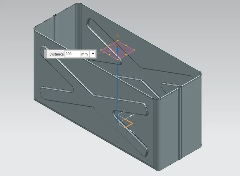
Now we have to create a lid on the body so by using a sketch on the newly created datum plane we create a tab of 1mm thickness that play a role as a lid on the box assembly. Then we add small flanges on the ends of the lid(tab) with 3mm length and 0.5mm bend radius
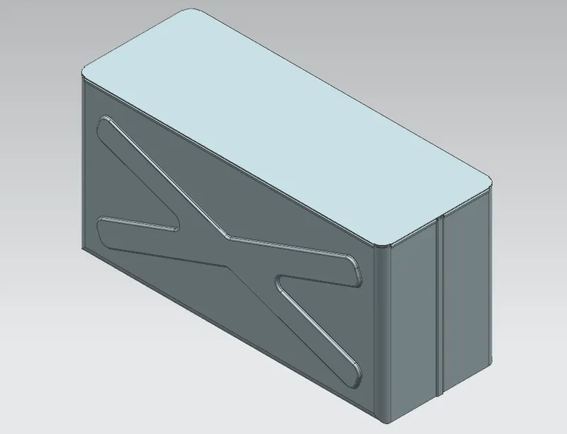
Here we created a lid, now we design hinges for the tab and the body created before. By using tab, break corner, flange and open loop hem we create below type of design which plays a role as hinges between the lid and body.
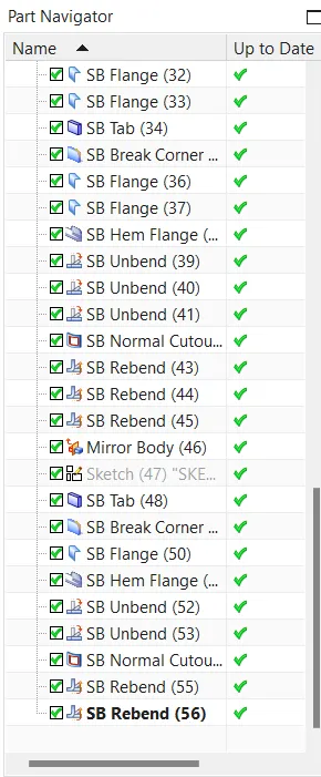
First We do a tab and apply break corner at an end. then we add a flange to the newly created tab and add another flnage with 42 deg angle. Now we apply an open loop hem flange of 5mm bend radius and 325 deg sweep angle. Now we unbend the whole from newly created tab to open loop hem, use normal cutout command to remove necessary region from the assembly. Then we rebend it and use mirror body command on newly created hinge by selecting XZ plane as reference.
Now we create another base feature tab on the lid and design another hinge by using flange, open loop hem flange and normal cutout option.
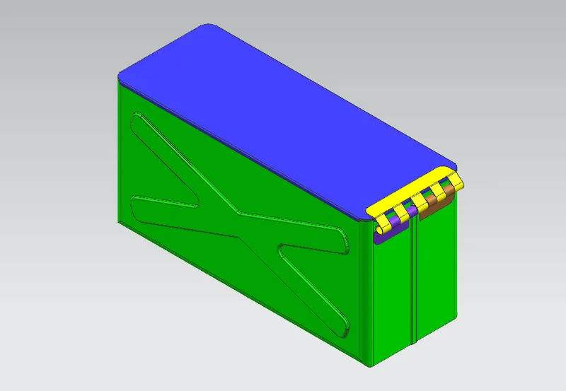
By completing the design of hinges we complete the design of box assembly by assigning the feature color to the assembly.
Different views of Box Assembly
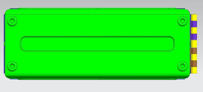
Top view
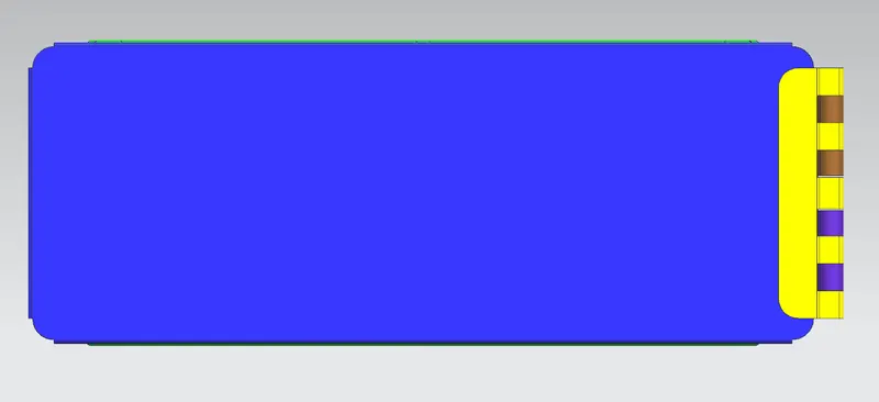
Side view
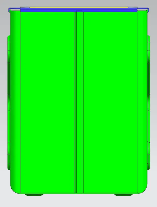
Front view
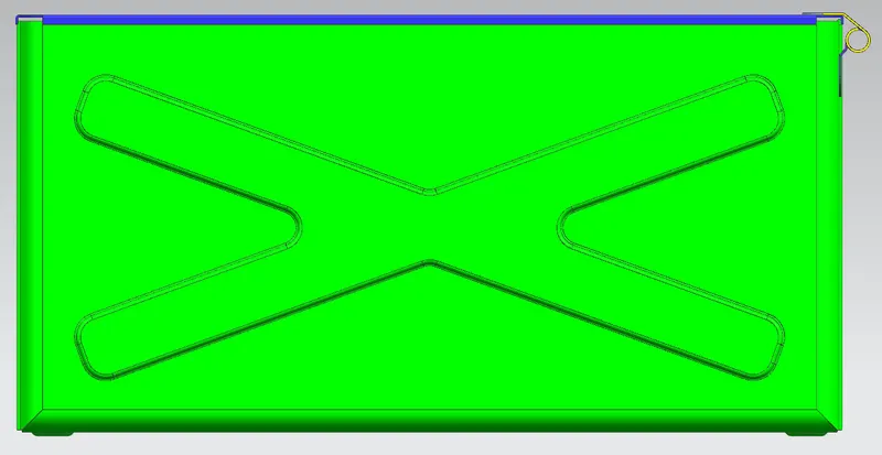
Bottom view
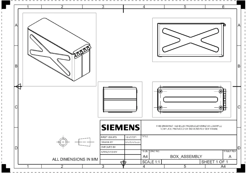
Drawing Sheet
Part navigator
Conclusion :
By completing the challenge of designing a Sheet metal Box assembly By using Sheetmetal Application of Siemens NX, I've learned about various tools used in completing this challenge and got familiar with using different features in Sheet metal application of NX.