Advanced Sheet Metal Design Using NX Cad Challenge_6_Bracket
Advanced Sheet Metal Design Using NX Cad Challenge_6_Bracket
Objective :
The objective of this challenge is to design a bracket from 2d drawing by using sheet metal application of Siemens NX and get more knowledge of the tools used in this challenge.
Introduction :
A simple rigid structure in the shape of an L, one arm of which is fixed to a vertical surface, the other projecting horizontally to support a shelf or other weight
OR
In mechanical engineering a bracket is any intermediate component for fixing one part to another, usually larger, part.
Brackets can support many architectural items, including a wall, balcony, parapets, eaves, the spring of an arch, beams, pergola roof, window box, or a shelf. Brackets are one of the most useful attachments in any vehicle. These brackets are used to hold heavy items or save bumpers from getting damaged. One such bracket that is most commonly used is the cross member assembly bracket.It is subjected to different types of loading while the vehicle is in motion. One of the main common
loading is static load which is assumed to be constant throughout the operation. This static load is main causes
for the failure of bracket. To reduce the failures stress concentration needs to be reduced at vicinity of the joint
hole of the bracket, as the hole is highly stressed region
Design Methodology :
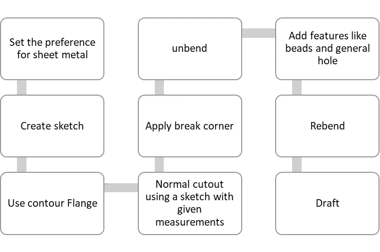
The design process of the bracket is given in below flow chart.
Description :
All the tools used while doing this challenge are as follows.
Sketch : Sketch command to create a sketch and define its sketch plane, orientation, or origin. You can create a sketch on an edge, curve, datum plane, or planar face.
Contour flange : Use the Contour Flange command to create a flange by extruding a sketch along a vector, or by sweeping a sketch along an edge or chain of edges. NX adds bends automatically using the default bend radius value. To use a different bend radius value, draw arcs in the section, or change the default bend radius value.
You can use the contour flange as the base feature of a new sheet metal part, or add the contour flange as a secondary feature.
Normal Cutout : Use the Normal Cutout command to cut material by projecting a sketch onto the model and then cutting perpendicular to the faces intersected by the projection.
You can use planar sketches or 3D curves to specify the section for the normal cutout.
Break Corner : Use the Break Corner command to round or chamfer sharp corners of a tab or flange.
Unbend : Use the Unbend command to unbend a portion of the part to construct cutout features, hole features, or deform features across a bend. You can later reform the bend to represent the true formed state of the model.
Bead : Use the Bead command to lift material along the contour of a sketch that simulates a stamping tool. Beads can also be created to stiffen sheet metal parts.
Hole : Use the Hole command to add the following types of hole features in a part or assembly:
-
General holes (simple, counterbored, countersunk, or tapered form)
-
Drill Size holes
-
Screw Clearance holes (simple, counterbored, or countersunk form)
-
Threaded holes
-
Holes on non-planar faces
-
Holes through multiple solids as a single feature
-
Multiple holes as a single feature
Rebend : Use the Rebend command to return an unbend feature to its previous bent state. Any features added after the unbend operation are properly repositioned during the rebend operation.
Process :
- First we set the preference for the sheet metal
- Now make a sketch in XY plane.
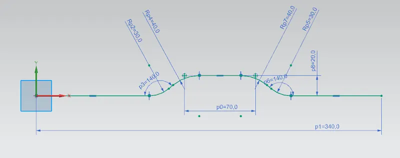
- By using the sketch as reference we apply contour flange with given measurements
- After the contour flange we make another sketch in xy plane with given measurements and use it as reference to make a normal cutout.
- Then we use Break corner on the mentioned edges with approriate measurements.
- Now we apply unbend command and make a bead with given measurements.
- Then we make simple general hole normal to face by using sketch section and rebend the sheet metal part.
Images :
Sketch for Contour flange
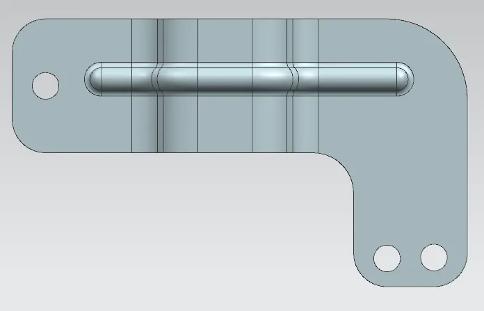
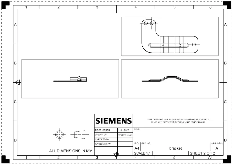
Front
Side

isometric
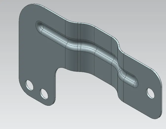
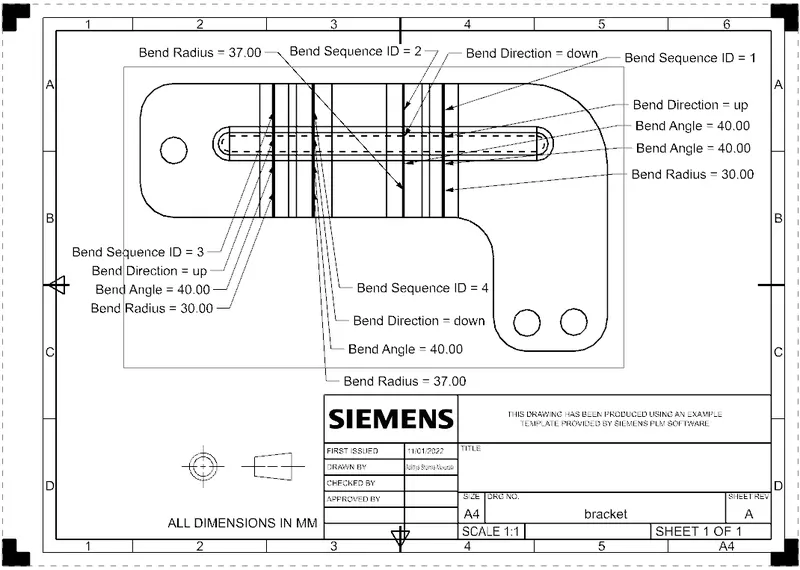
Draft
Conclusion :
By completing this challenge of design of bracket in sheet metal application of Siemens NX, I've come to know a great deal about the tools used in completing this challenge like contour flange,normal cutout, bead, hole.