Wiring harness design in CATIA V5 - 3D modeling Week 5 & 6 Challenge
Aim - To route the given harness bundles.
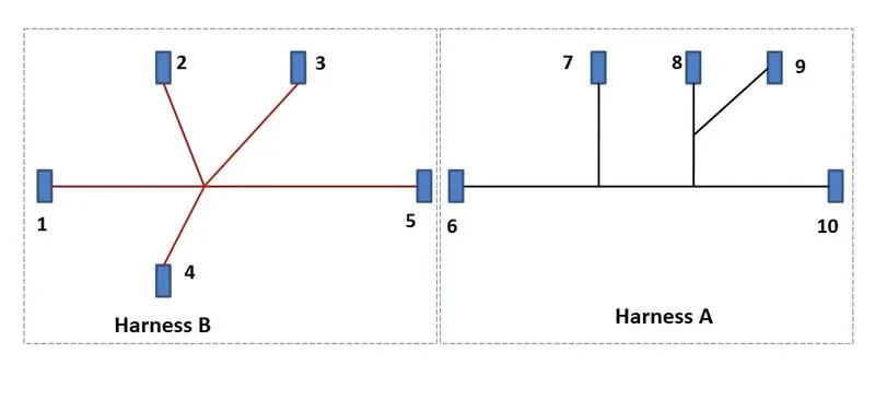
Given -
Harness A & B
Procedue -
HARNESS B
Creating the assembly -
- We first download all the connectors and define them as electrical components.
- We start by creating a new product. We name this product as Harness B and we export all the required connectors into the product.
- We then use the Assembly design workbench and place all the connectors in the given positions as shown in in the image above.
- We then go into the Electrical harness Assembly and define the Harness B as a geometrical bundle.
- Now we use the Multibranchable option and create all the Harness routings to the desired connector locations.
Bundle continuity -
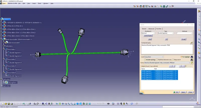
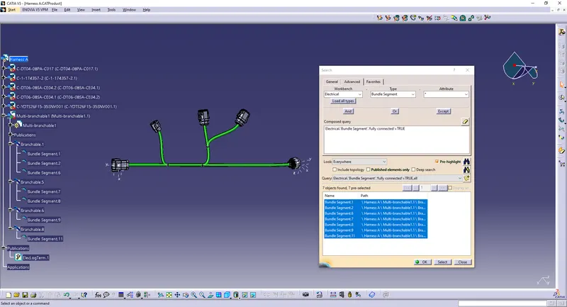
- We use the edit option from our toolbar and go to search.
- Here we select the workbench as electrical, the type as Bundle segment and the attribute as fully connected and choose the case as true in the search criterion.
- Now we hit the search button and it shows us all the connected bundles.
Bundle warning -
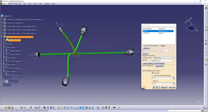
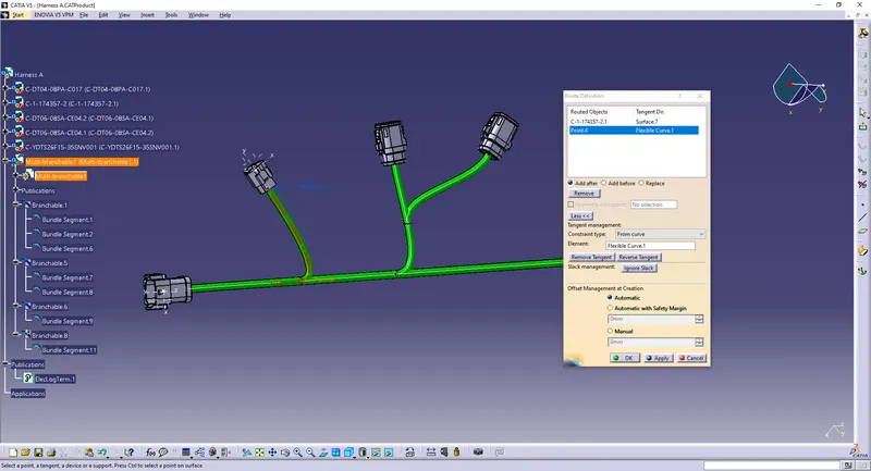
We get this error as a small yellow error on our feature tree and this is found in the branch definition option and inside route definition.
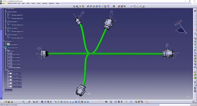
Annotations -
HANRNESS A
we follow all the same steps as we did for Harness B and create Harness A looking at the given image.
Bundle connectivity -
Bundle Warning -
Annotations -
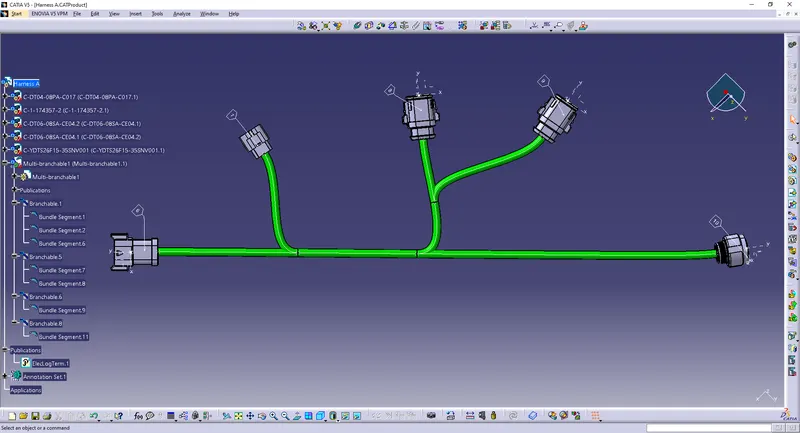
-> The respective .igs files can be found inside the respective assembly folders named Harness A and Harness B.