Wiring harness design in CATIA V5 - 3D modeling Week 5 & 6 Challenge
'Wiring harness design '
Input:
We have to route the following harness layout in Electrical workbench
Steps:
1) We have to define all the connectors geometrically and electrically
Harness B:
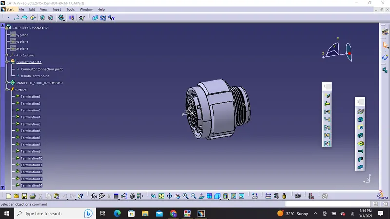
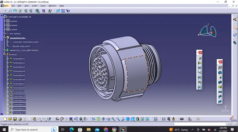
1) C-YDTS26F15-35SNV001 : No of termination is 37
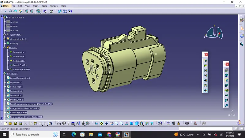
2) C-DT06-3S-CP01: No of termination is 3
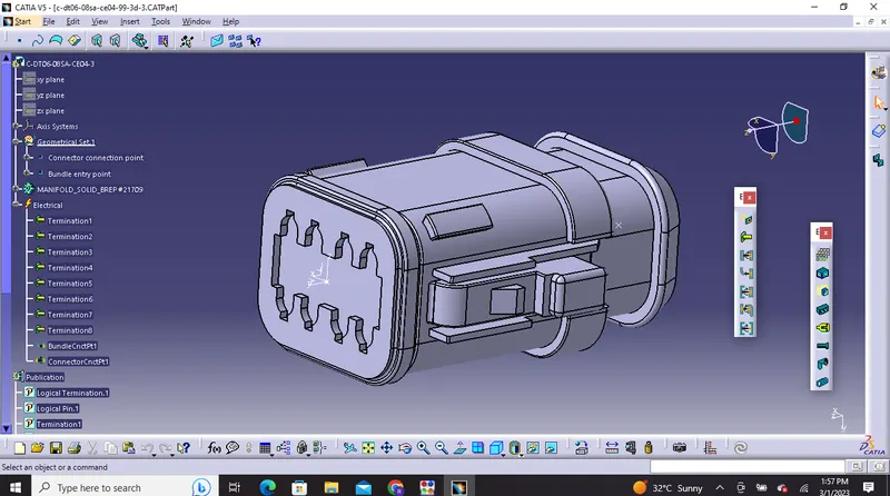
3) C-DT06-08SA-CE04: No of termination is 8
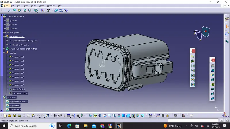
4) C-DT06-08SA-EP07: No of termination is 8
5) C-DT06-08SA-CE13: No of termination is 8
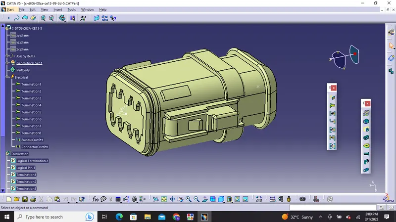
Harness A:
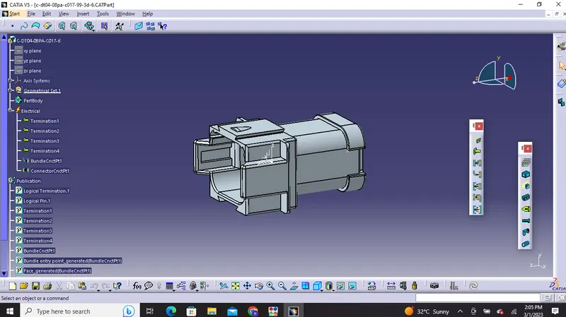
6) C-DT04-08PA-C017: No of termination is 4
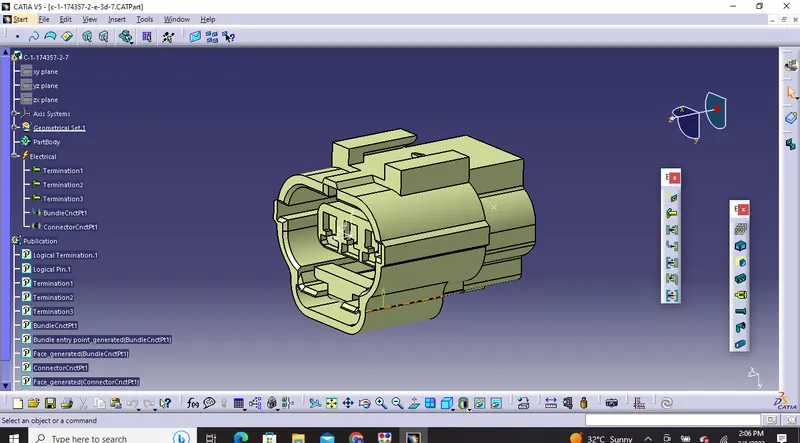
7) C-1-174357-2: No of termination is 3
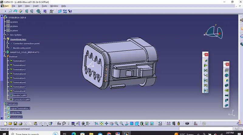
8) C-DT06-08SA-CE01: No of termination is 8
9) C-DT06-08SA-EP07: No of termination is 8
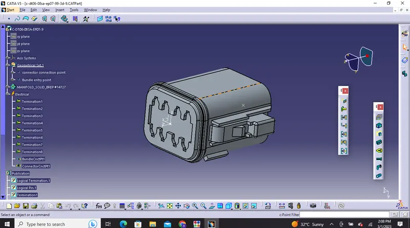
10) C-YDTS26F15-35SNV001: No of termination is 37
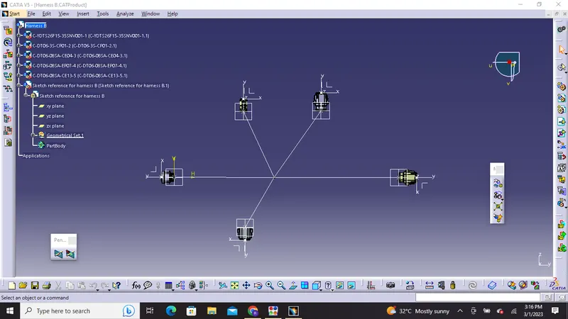
2) Now we have to locate all the connectors in the required position and create bundle segments for both the harness 'a' and 'b'
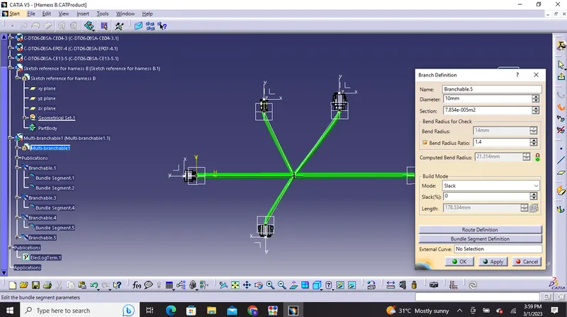
Harness B sketch routing
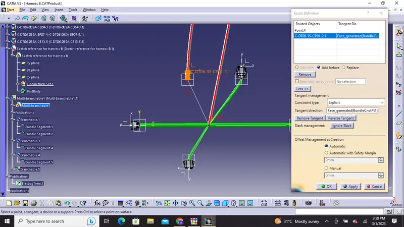
3)Bundle warning: In this we have to check the bundle warning and check the tree structure with yellow flash and we need to reverse it and correct it by modyfying any input factors.
4)Bundle continuity: we have to check bundle continuity in both Harness A and Harness B.In order to do that we have to click on Edit>Search>Workbench-Electrical>Type-Bundle segment>Attribute-fully connected. Then we will get one window where we have to select true condition option and search for results.
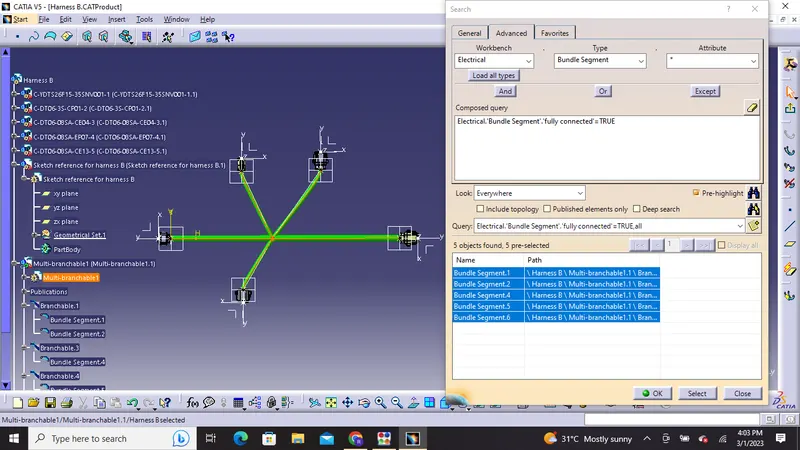
As the bundle segments are showing connected. So there is bundle continuity in Harness B
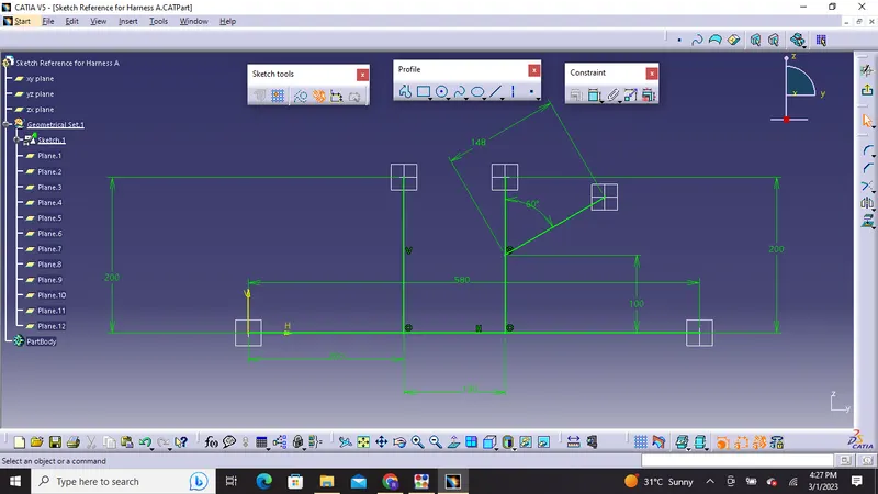
Harness A sketch routing:
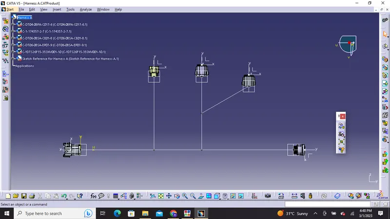
Harness A connector routing
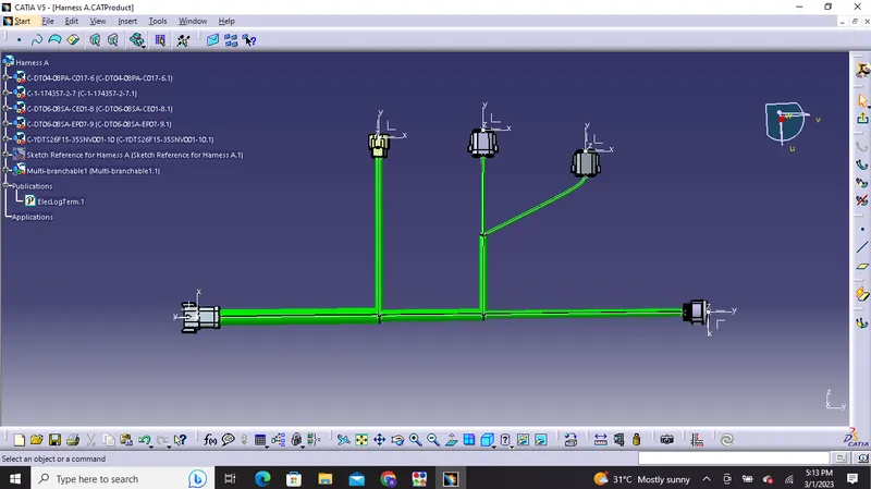
Bundle continuity: we have to check bundle continuity in both Harness A and Harness B.In order to do that we have to click on Edit>Search>Workbench-Electrical>Type-Bundle segment>Attribute-fully connected. Then we will get one window where we have to select true condition option and search for results.
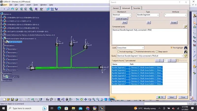
As the bundle segments are showing connected. So there is bundle continuity in Harness A
5)Assembly of connectors: We need to create one product file and add both the harness together by coping or inserting both harnesses in newly created product file.
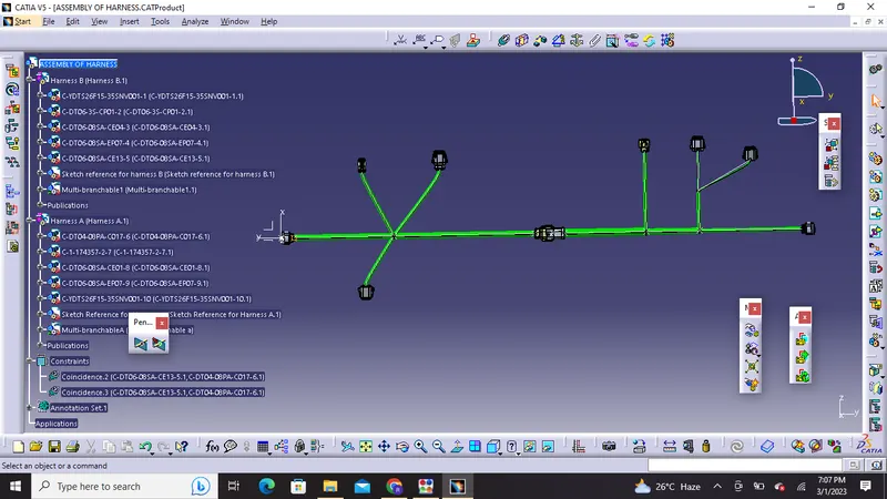
6) we have to go to Electrical Assembly Design workbench and use "connect electrical devices"
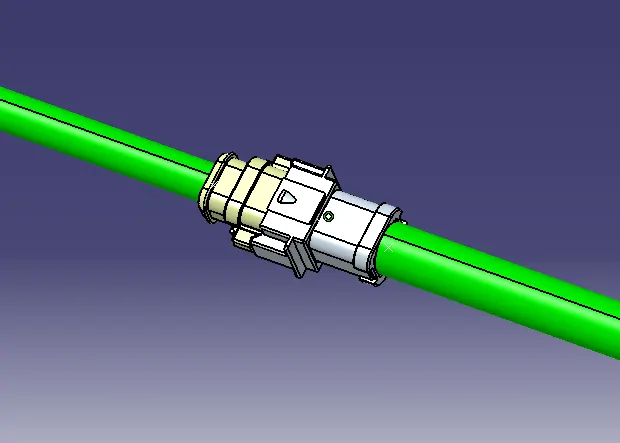
Electrically connected connectors
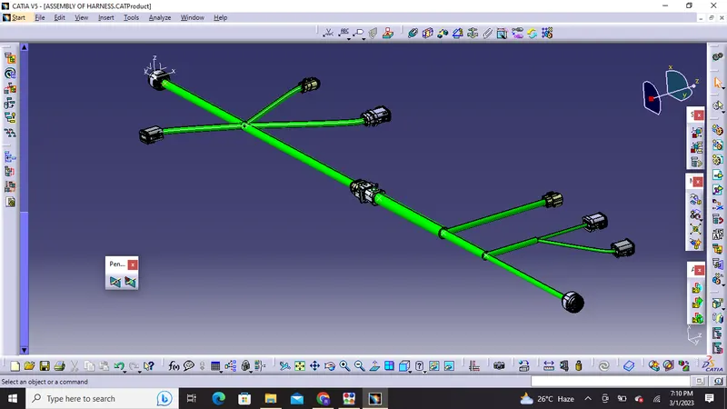
7)Annotations: They are used to show connector functions and additional information. We can define it in Assembly Design Workbench of CATIA V5.In order to do so first, we have to choose a plane on which the annotation will be placed and add define that area using text as per numbering or alphabets.
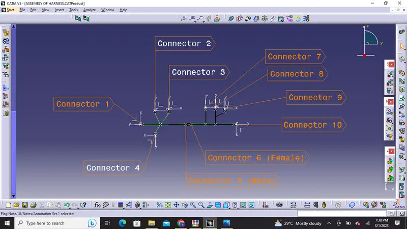
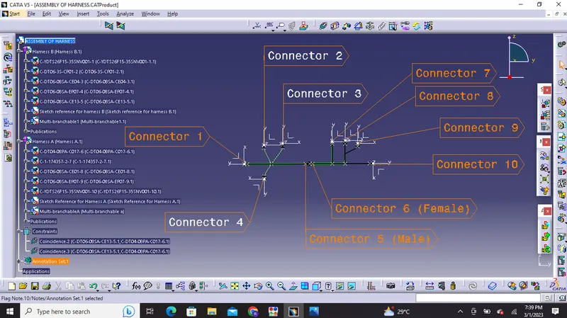
8)Generation of cat part from product: In this step we have to convert final harness assembly file into IGS format. So for that we need to follow following steps:
- Mechanical Assembly Design workbench>Tools>Generate CAT Part from product.
- Once the CAT part is created, the whole product file is converted into a single part.
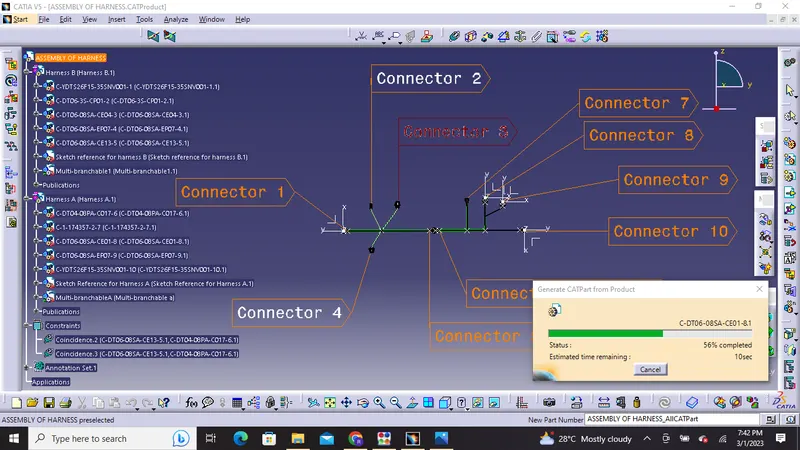
Mechanical Assembly Workbench>Tools>Generate CAT Part from product
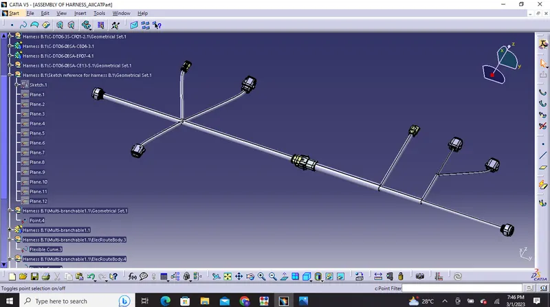
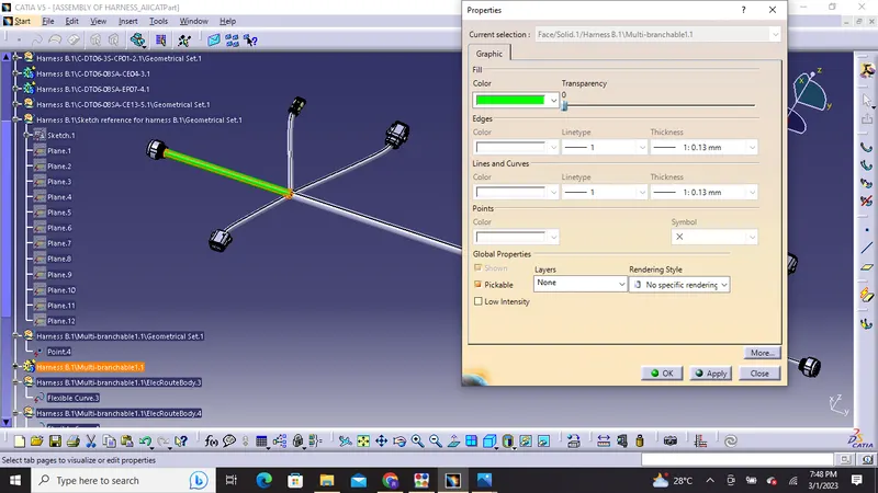
Once the CAT part is created the whole product file is converted into a single part. At this stage, it can be noticed that all the bundle segments are grey in color. So, we will go back and add green color to each bundle segment so that they look same as the Final Harness Assembly.
Then we will change it to green color
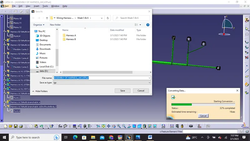
9)In the end, we can use the "SAVE AS" feature to save the CAT part file as IGS file as shown below.
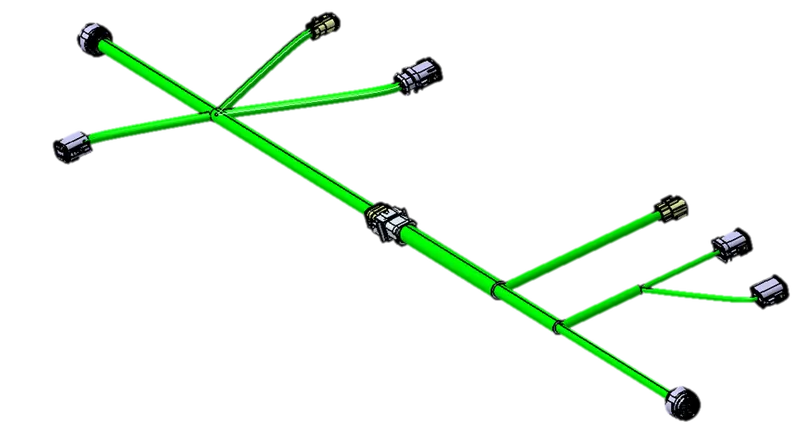
Output:
Thank you!