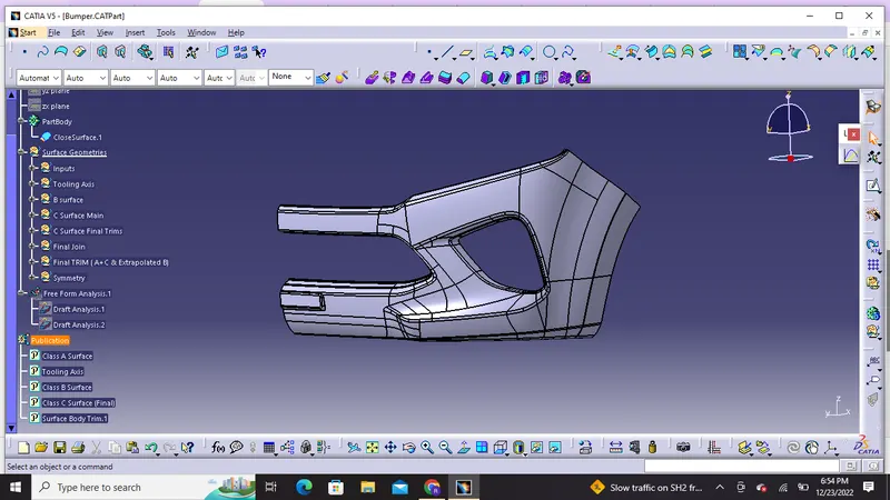
Week 8 - Challenge 4 - Bumper
Bumper Design & Analysis
Bumper: A bumper is a structure which is attached to front and rear ends of a four wheeler to absorb small impacts during collison but with time many sensors , body parts such as lights and aesthetic surfaces such as grills are also attached to it making it better in looks and loaded with features.
Materials blends which are used for manufacturing bumpers are ABS ( Acrylonitrile Butadiene Styrene),Polycarbonate,Polypropylene etc.
Input :
Class A Surface:
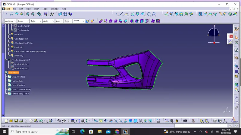
Class B surface:
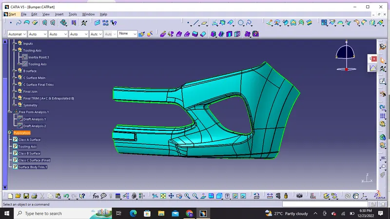
Class C Surface
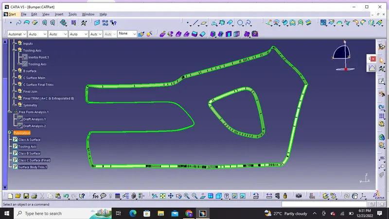
Tooling Axis
We can make tooling axis by center point on the model and using intersection we can create bisecting lines and bisecting line will bisect the two lines if they are perpendicular and will show some error if they are parallel this will decide that whether the surface is toolable or not and then perform draft analysis on it as we performed on previous projects.
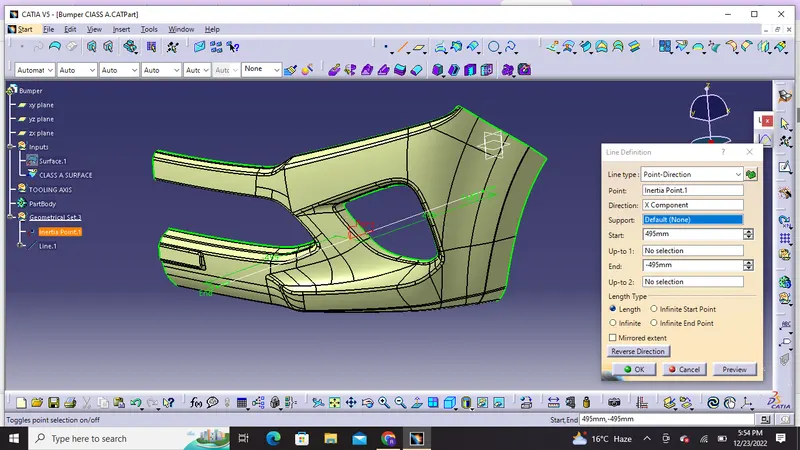
But for Tooling axis creation in complex and large parts like bumper we can also draw tooling axis in the centre of gravity point using inertia method as The centre of gravity is a point in an object where the distribution of weight is equal in all directions and this point will be suitable for the direction of extraction of component very easily. Then we can view the component in all directions and for this bumper x direction will be best for creation of tooling axis using the centre of gravity point.
Steps for inertia method are as follows:
1) We will click on measure inertia button which is beside measure item .
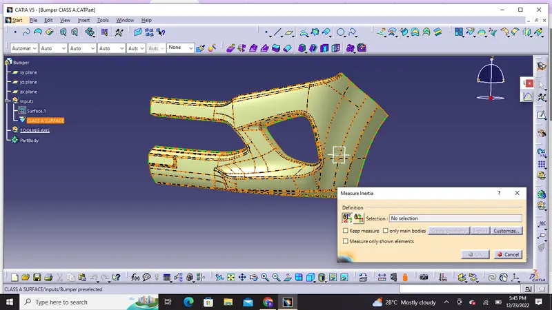
2) After selecting Class A surface we will next click on create geometry
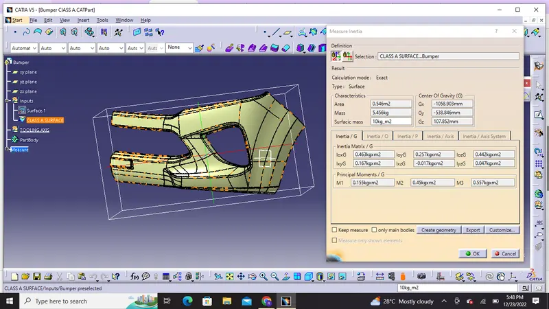
3) Furthermore we will click on non associative geometry and select centre of gravity and press ok
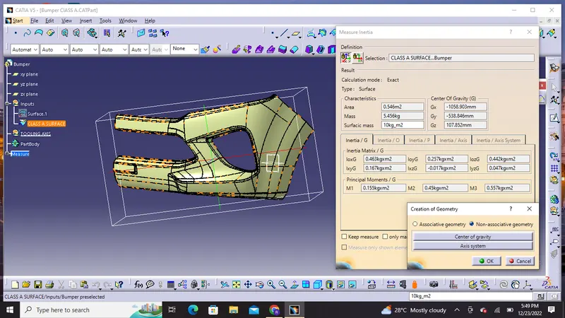
4) The inertia point will be created
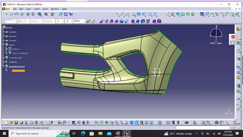
5)We will select a line and select point and direction in which inertia point and x direction is choosed for final creation of tooling axis.
Draft Analysis:
Draft is the angle in which the part is tapered to allow it to release from the mold properly and as the part is cooled it has a tendency to shrink towards the core side of the mold due to this we need to add draft angles.Nominal draft angles is usually around 3 degrees and more than 3 degrees can also be manufactured like 5 degrees but it will unecessarily increase the costing of manufacturing and final product.
Procedure used for draft analysis in Catia cad software:
1) In display frame first we need to change it to material mode
2) Click on insert then analysis and select feature draft analysis
3) Then we will click on compass and and align it with tooling direction.
4) Then we will click on the lock symbol and then click on the surface of the part the colour will change
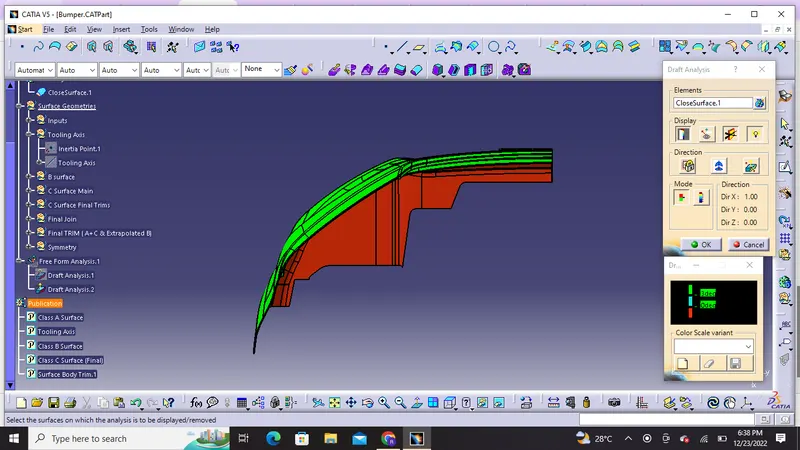
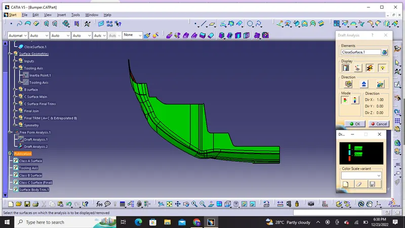
5) Different color codes are identified and there we can apply draft angle which will reflect us minimum draft angle in green color.
6) We can also have running point analysis on different regions of the part body for permissible draft angle.
Draft analysis report for Class-A surface:
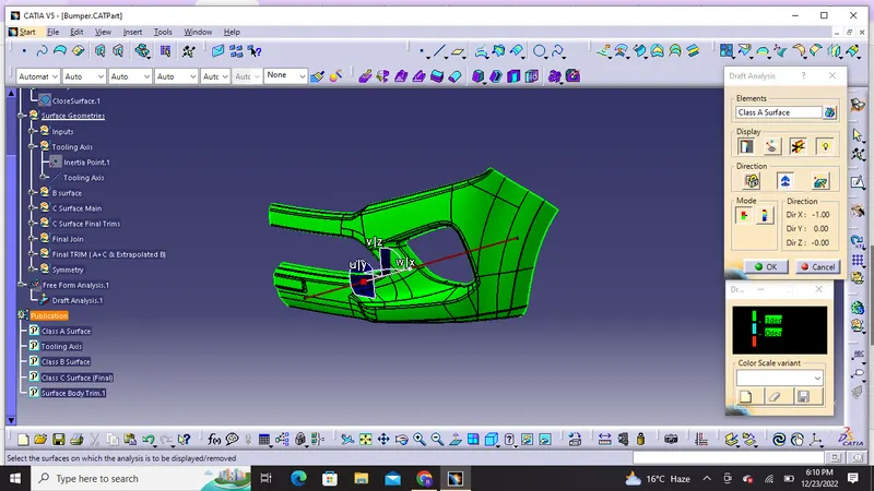
Minimum 3 degree Draft
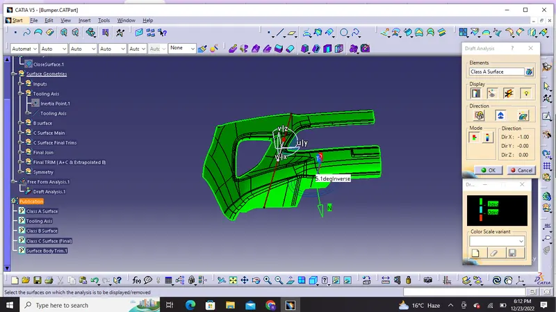
Running Point Analysis on Class A surface Inner side
Draft analysis report for Final Plastic component ( BUMPER)
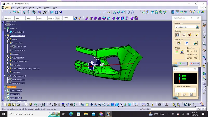
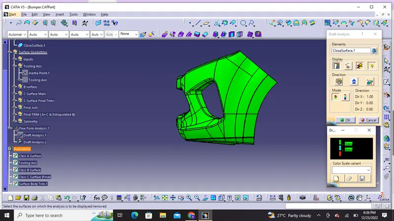
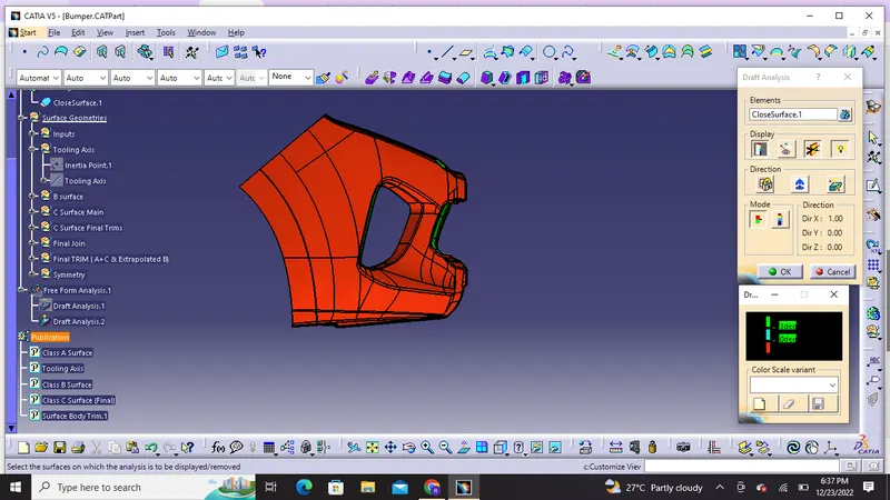
Minimum 3 Degrees Draft
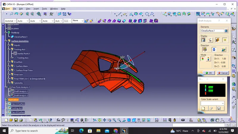
Draft Analysis Back side of bumper
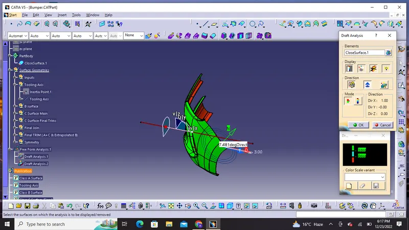
Running point Analysis
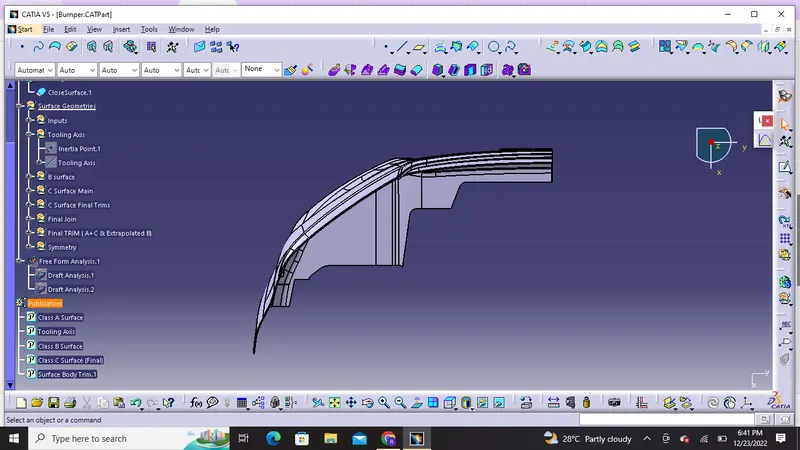
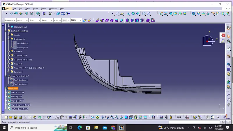
Different views of the solid body in various orientations :
1) Isometric View:
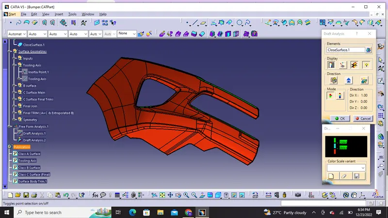
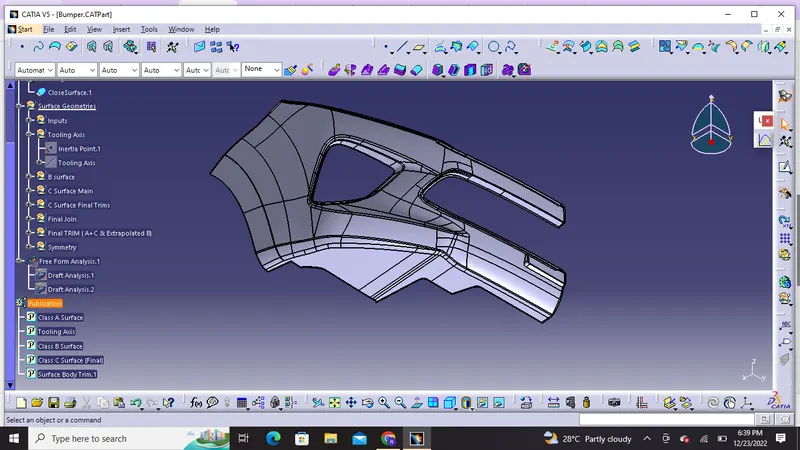
2) Front View
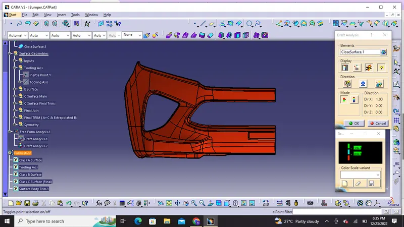
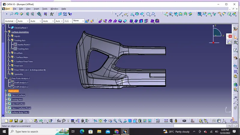
3) Back View
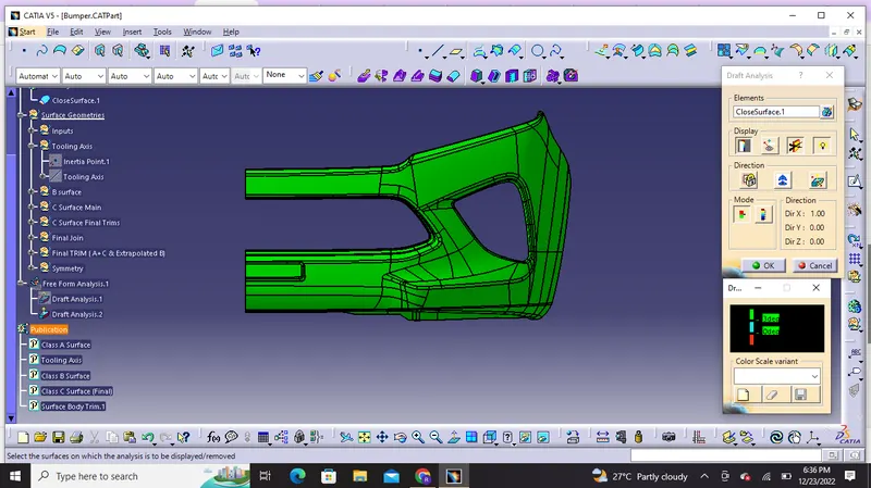
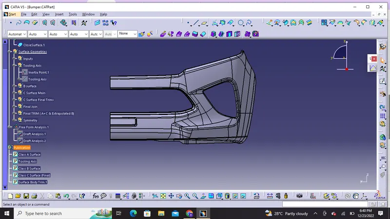
3) Side View
Left View
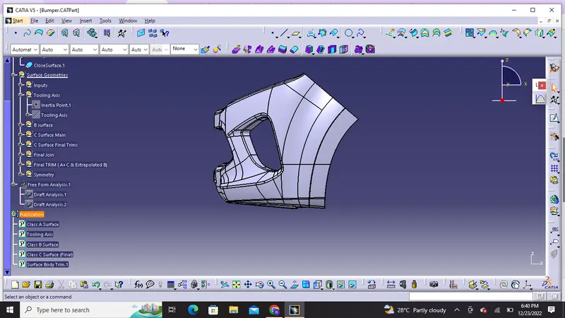
Right View
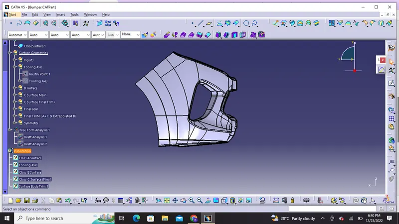
4) Top View
5) Bottom View
Final Component
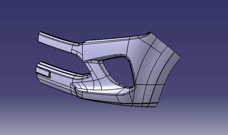
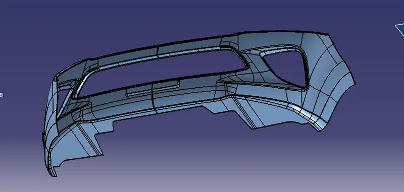
Final Outputs :
Thickness of component : 3mm
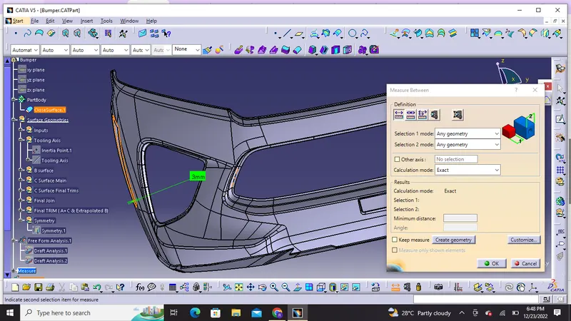
Surface Body : Surface body with closed boundary
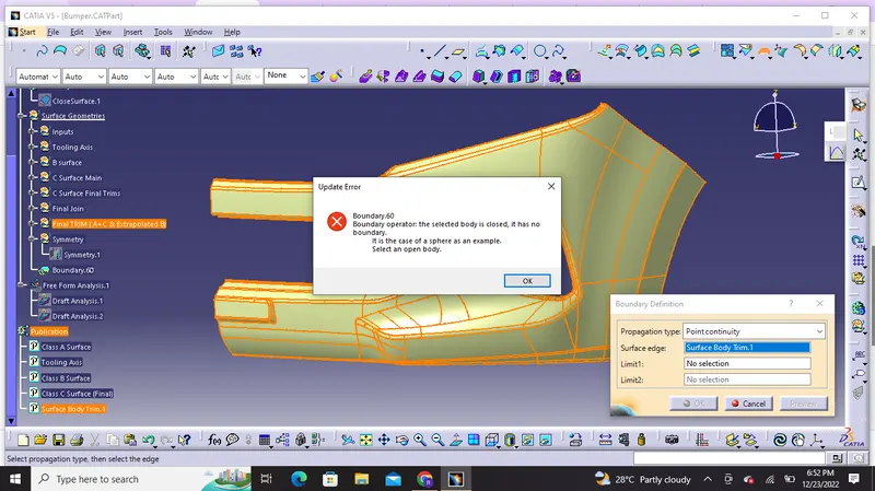
Tree structure with following parameters:
1) Part Body : Closed surface
2) Surface geometries : ( Class A ,B ,C and all the trims and design features)
3) Publications :
- Class A surface
- Tooling Axis
- Class B surface
- Class C surface
- Surface body