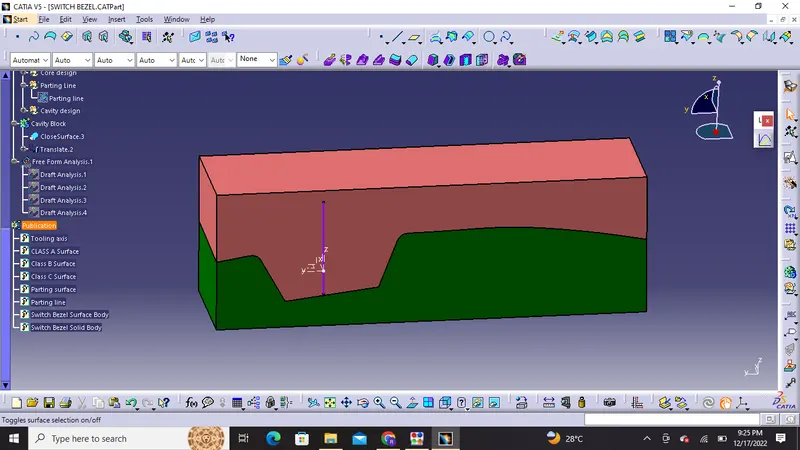
Week 8 - Challenge 6 - Core & Cavity Design
Core & Cavity Design on Switch Bezel
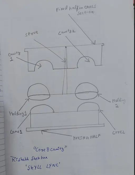
CORE : It is the male portion of the mold which creates the internal shape of the plastic component and is also the moving half of the injection mold machine.
CAVITY : Cavity is the female portion of the mold which creates the external plastic part surface.It is generally fixed half in cross section.
Tooling Axis:
For tooling axis creation Class A surface is first investigated. In plastic product design tooling direction is essential as it decides the direction for separation of mould.
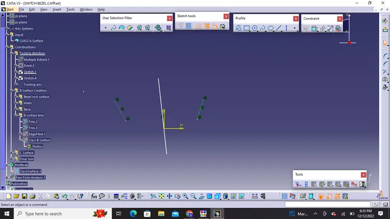
In this Part design we had only 3 walls so we cant diretly use bisecting method we have to draw tooling axis through sketch method and then use bisection along the axis .
1)we will Draw dummy tooling axis along Y direction
2) Then we will Take intersection of class A surface and draw two llines and create bisecting lines
For X direction we will again intersect and follow the same method
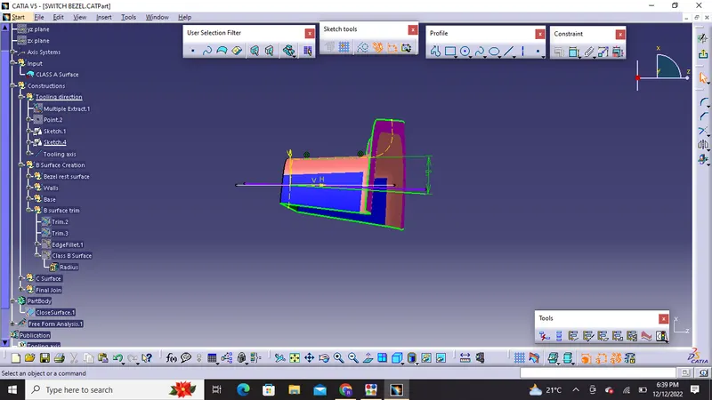
The two mean line are finally bisected for creation of tooling axis:
Bisecting method is used to find tooling axis using dummy tooling axis this bisecting line will bisect the two lines if they are perpendicular and will show some error if they are parallel this will decide that whether the surface is toolable or not .
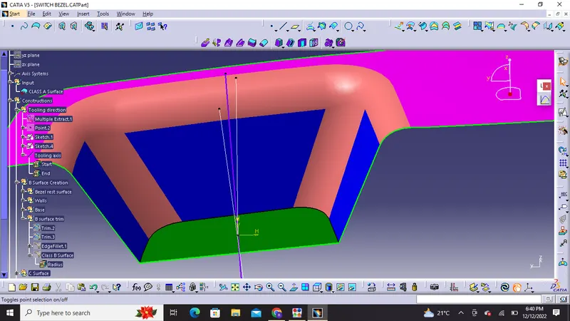
Final Tooling axis
Draft Analysis:
Draft is the angle in which the part is tapered to allow it to release from the mold properly and as the part is cooled it has a tendency to shrink towards the core side of the mold due to this we need to add draft angles.Nominal draft angles is usually around 3 degrees and more than 3 degrees can also be manufactured like 5 degrees but it will unecessarily increase the costing of manufacturing and final product.
Procedure used for draft analysis in Catia cad software:
1) In display frame first we need to change it to material mode
2) Click on insert then analysis and select feature draft analysis
3) Then we will click on compass and and align it with tooling direction.
4) Then we will click on the lock symbol and then click on the surface of the part the colour will change
5) Different color codes are identified and there we can apply draft angle which will reflect us minimum draft angle in green color.
6) We can also have running point analysis on different regions of the part body for permissible draft angle.
Draft analysis report on Class A surface (Switch Bezel)
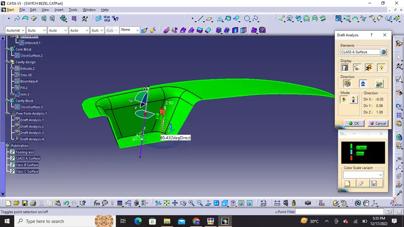
Minimum Draft value 2.99 degrees
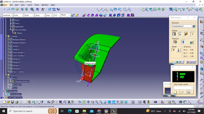
On inversing the draft direction the color changes
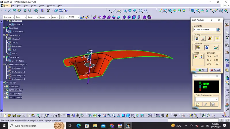
Draft Analysis Report on plastic part (Switch Bezel)
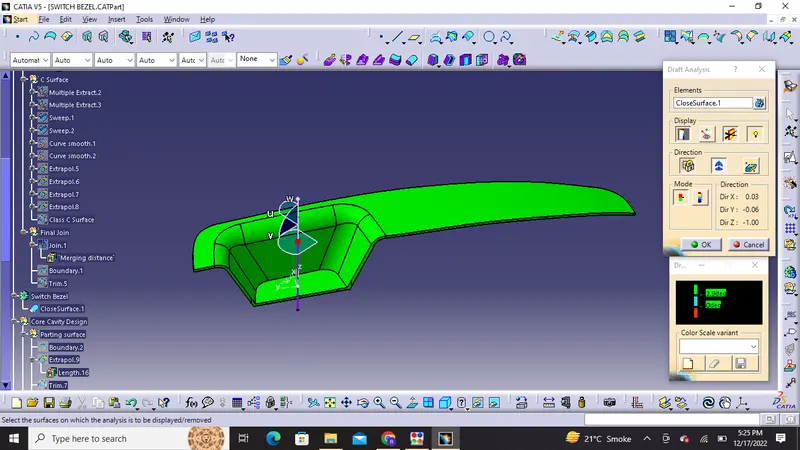
Running point analysis around 3 degrees in green part
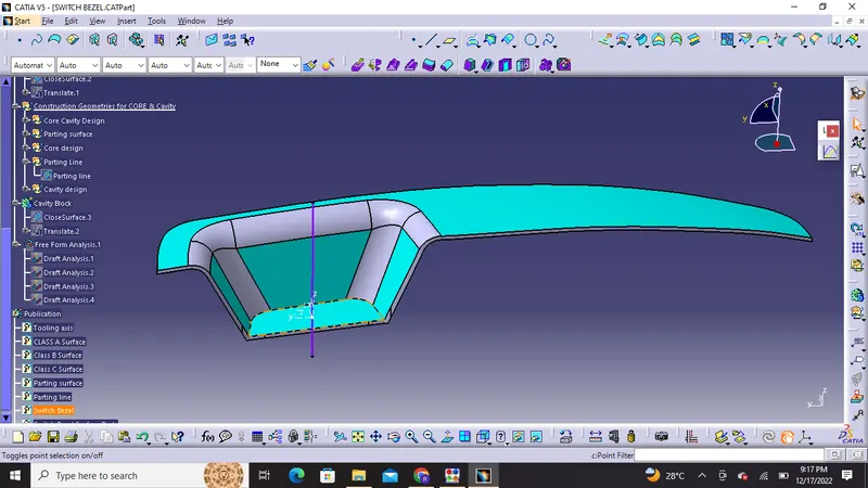
Parting line is intersection between parting surface and component that is were core and cavity have splits together .
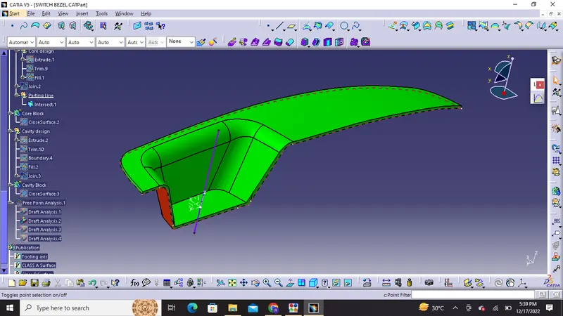
The brown dotted line in the above image is the parting line
Parting surface : It directly affects the product quality ease of construction and operation of the injection mold. The movable half and fixed half of the injection mold are pressed tightly to form seal in order o avoid the melt flow leakage and maintain certain holding pressure this presed surface is called parting surface.
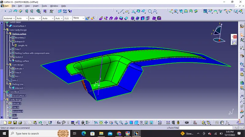
The above image shows Parting surface ,parting line,draft ,tooling axis all together
Tree structure with construction geometries and part body :
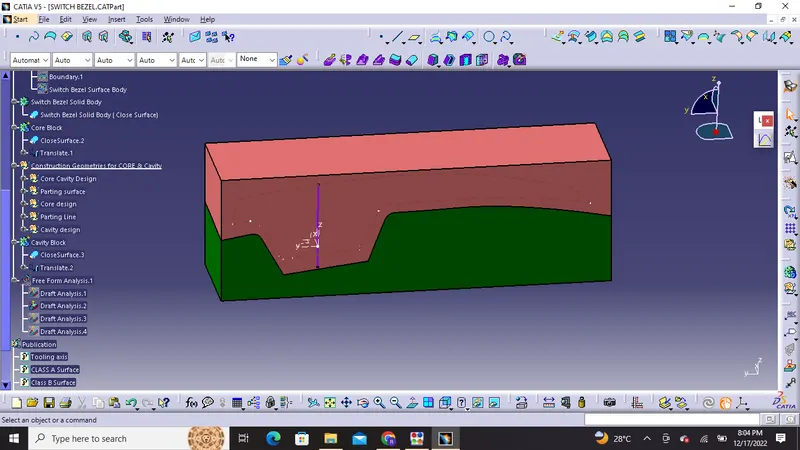
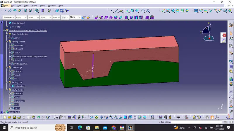
Orientations of core block
1) Isometric view
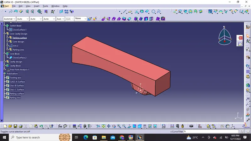
2) Front view
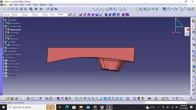
3) Side view
Left view
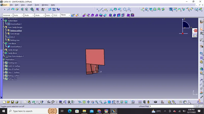
Right view
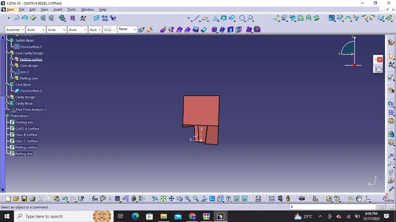
4) Top view
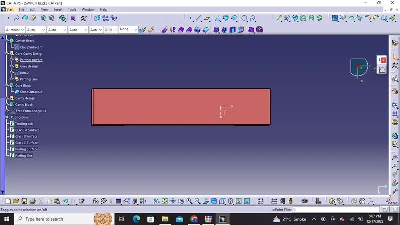
5) Front view
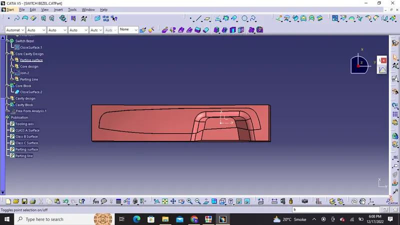
CORE BLOCK
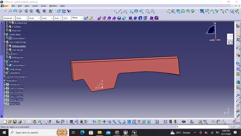
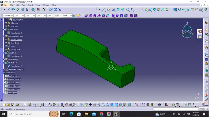
Orientations of cavity block
1) Isometric view
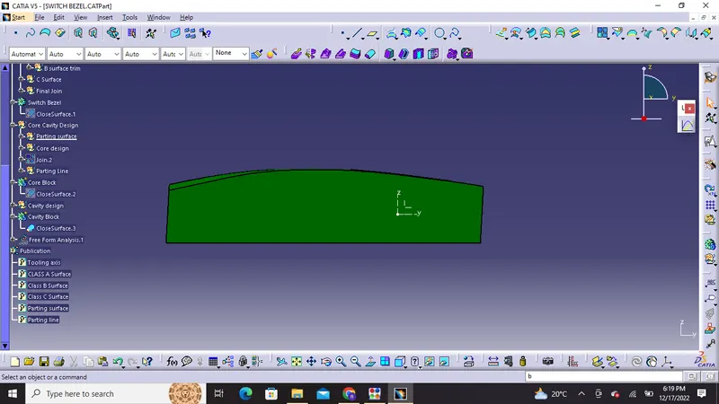
2) Front view
3) Side View
Left View
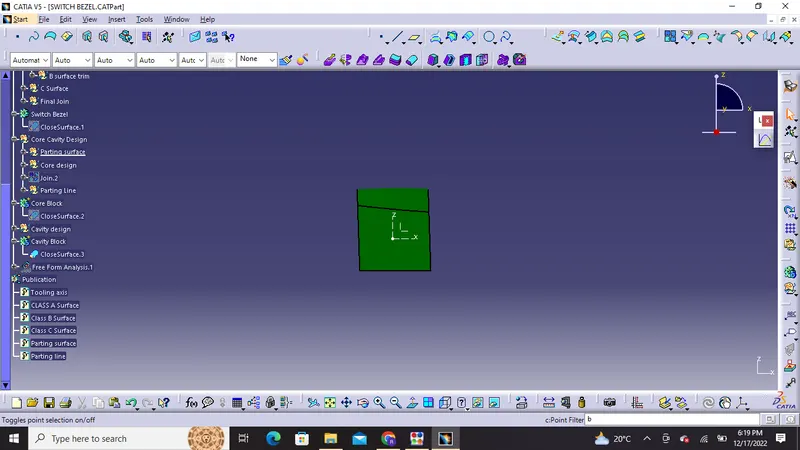
Right view
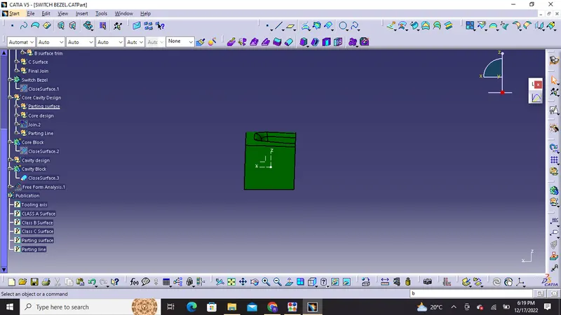
4) TOP VIEW
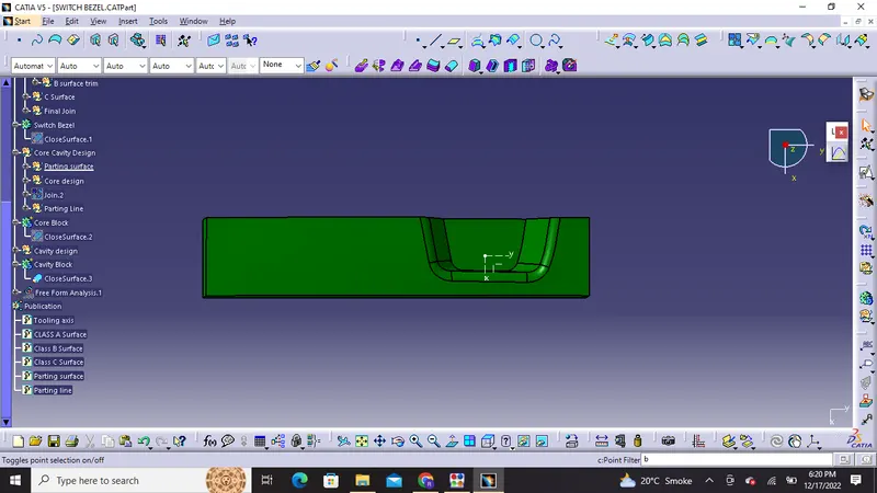
5) Bottom view
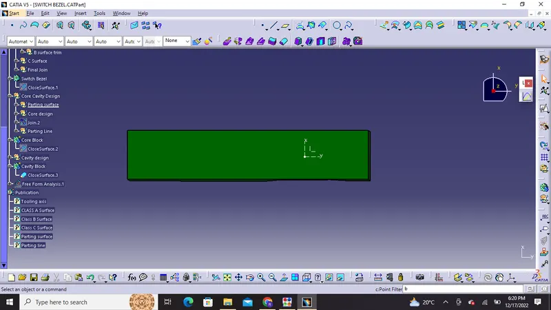
Cavity Block
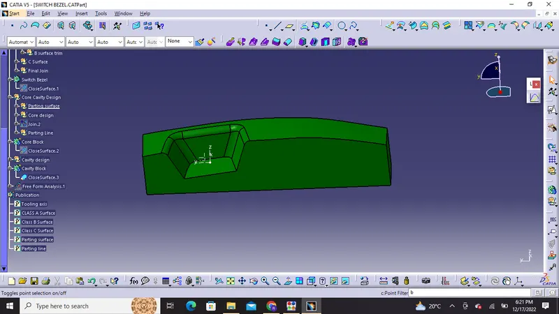
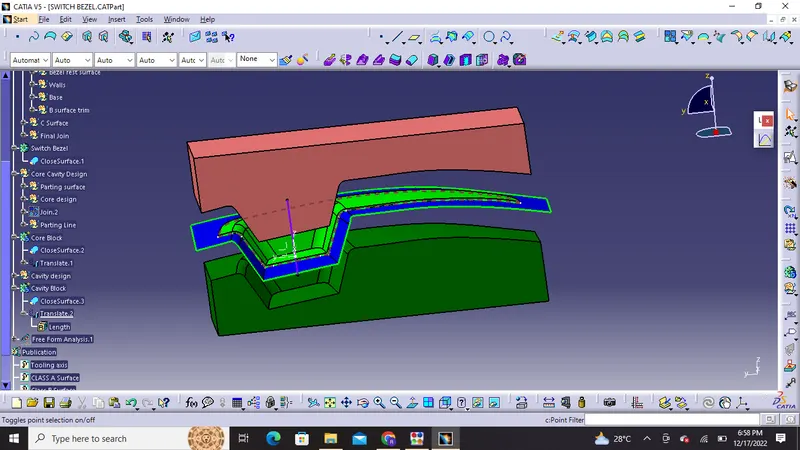
Using translate we can examine how the core and cavity will mate and what will be the final product
Publications:
- Tooling Axis
- Class A surface
- Class B Surface
- Class C Surface
- Parting Surface
- Parting Line
- Switch Bezel ( Solid Body)
- Switch Bezel ( Surface Body)