Week 8 - Challenge 1 - Base Bracket Design
Base Bracket Design & Analysis
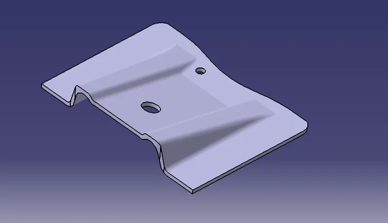
Class A Surface is one of the most important input in automobile industry specially in plastic design and is also one of the stages of design life cycle usually class A surfaces are created in Autodesk Alias for sketching concept modelling and visualization and then New product development in cad software is carried out. Class A is an aesthetic surface.
Class A surface:
Class B surface:
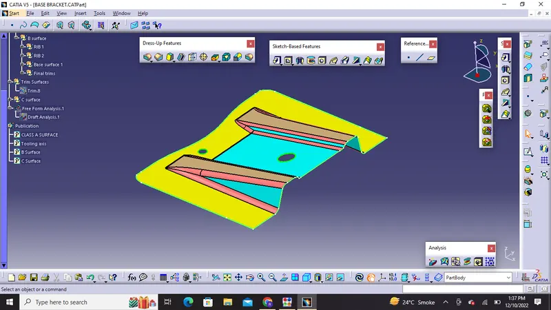
B surface is the surface which gives us thickness from the class A surface, Class B is the engineering surface as all the engineering features like ribs ,boss etc are made on this surface.
Class C Surface:
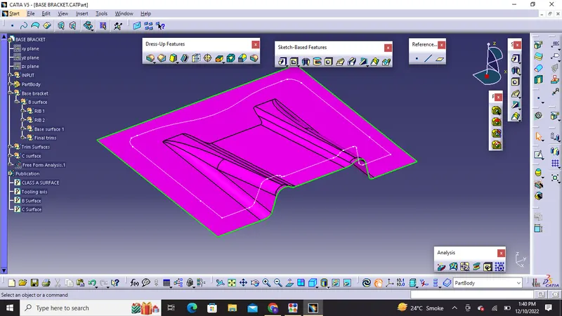
C surface is the surface which connects A and B along the tooling direction and is called Class C surface.
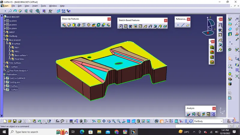
Tooling Axis:
For tooling axis creation Class A surface is first investigated. In plastic product design tooling direction is essential as it decides the direction for separation of mould.
Procedure:
We have to look at the best direction out of x , y and z where there would be no obstruction in this component the best direction is along z as the two holes on the top will be cleared
1) Firstly we make a dummy tooling axis direction with reference points as it makes us clear about the x y and z directions.
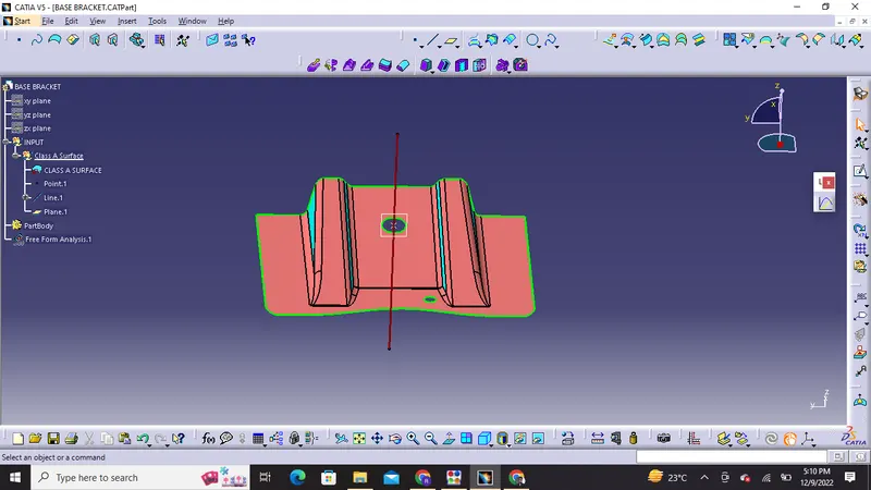
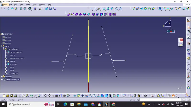
2) Take reference plane and intersect body with it to create bisecting lines for creating main tooling axis
The faces which are perpendicular to the tooling axis will clear easily whereas the problem can arise with the parallel faces so we will create point to point line and then create a bisecting line between them to check the clearance and degree of tooling axis.
Bisecting method is used to find tooling axis using dummy tooling axis this bisecting line will bisect the two lines if they are perpendicular and will show some error if they are parallel this will decide that whether the surface is toolable or not .
Draft Analysis:
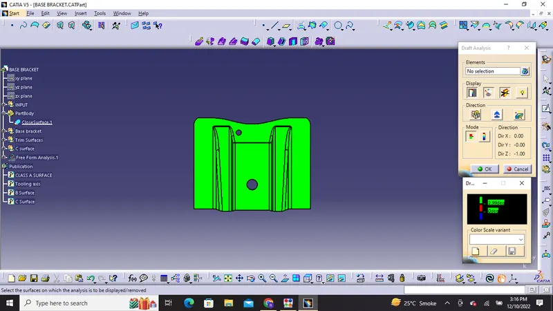
Draft is the angle in which the part is tapered to allow it to release from the mold properly and as the part is cooled it has a tendency to shrink towards the core side of the mold due to this we need to add draft angles.Nominal draft angles is usually around 3 degrees and more than 3 degrees can also be manufactured like 5 degrees but it will unecessarily increase the costing of manufacturing and final product.
Procedure used for draft analysis in Catia cad software:
1) In display frame first we need to change it to material mode
2) Click on insert then analysis and select feature draft analysis
3) Then we will click on compass and and align it with tooling direction.
4) Then we will click on the lock symbol and then click on the surface of the part the colour will change
5) Different color codes are identified and there we can apply draft angle which will reflect us minimum draft angle in green color.
6) We can also have running point analysis on different regions of the part body for permissible draft angle.
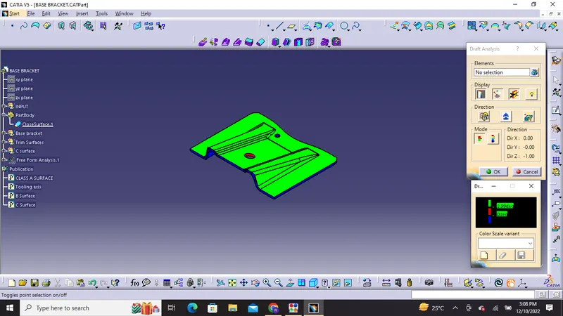
Draft analysis report for Class-A surface:
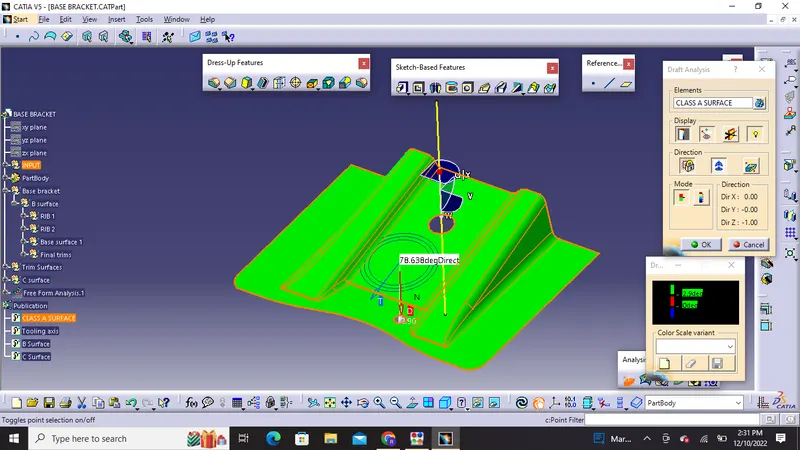
Minimum Draft of 2.9 Degree
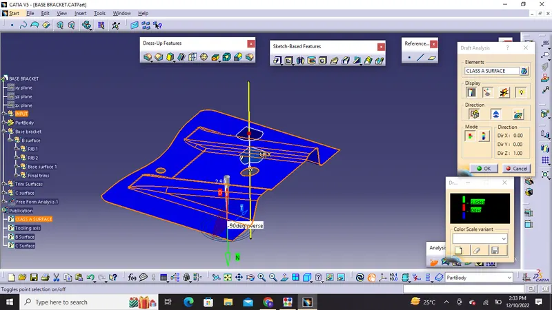
On Inversing the draft direction the color changes to blue
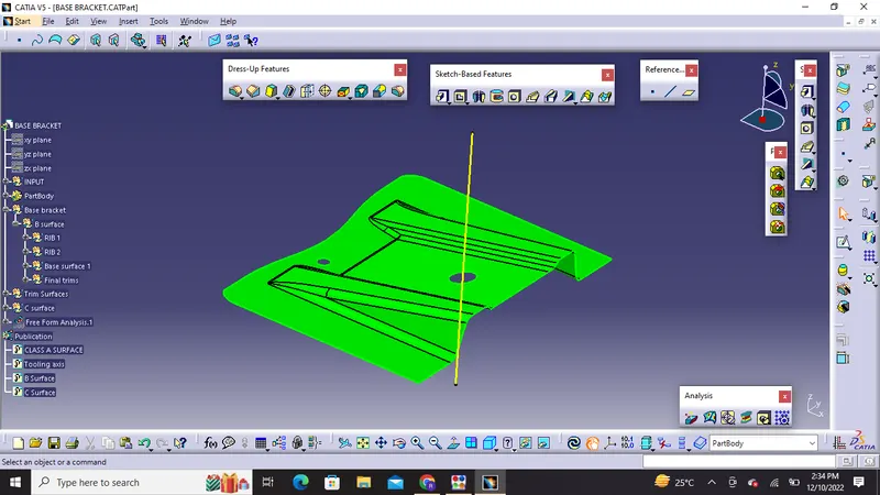
Draft analysis report for Final plastic product (SWITCH BEZEL) :SOLID BODY
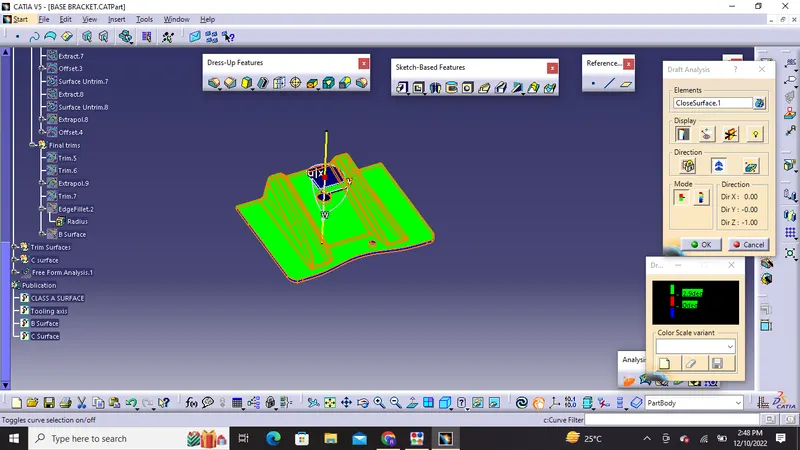
Minimum Draft is 2.99 Degree
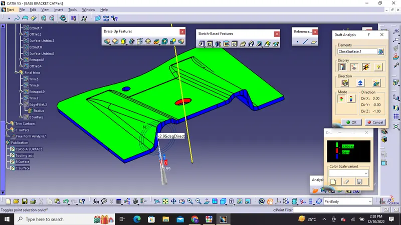
Highlighted surface indicates 2.95 degree

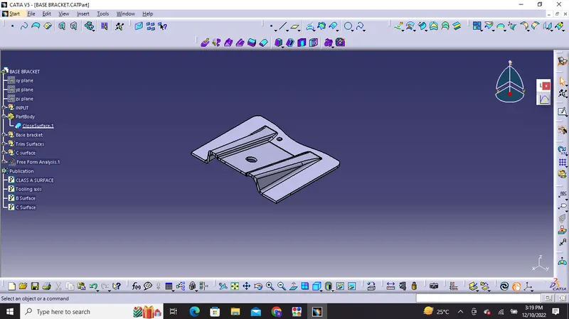
Different views of the solid body in various orientations :
1) Isometric View:
2) Front view
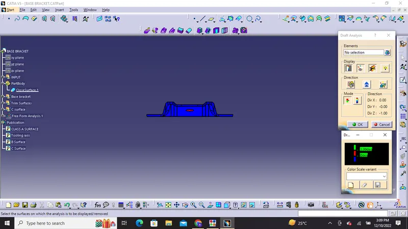
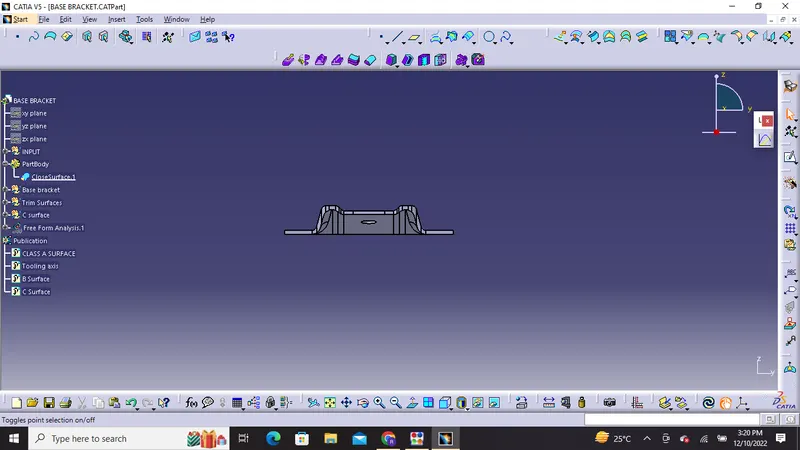
3) Left view
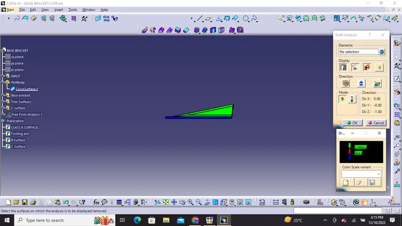
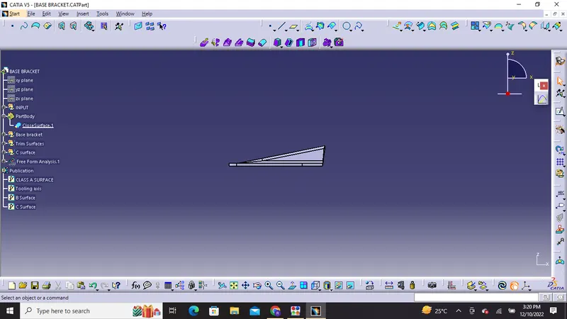
Right view
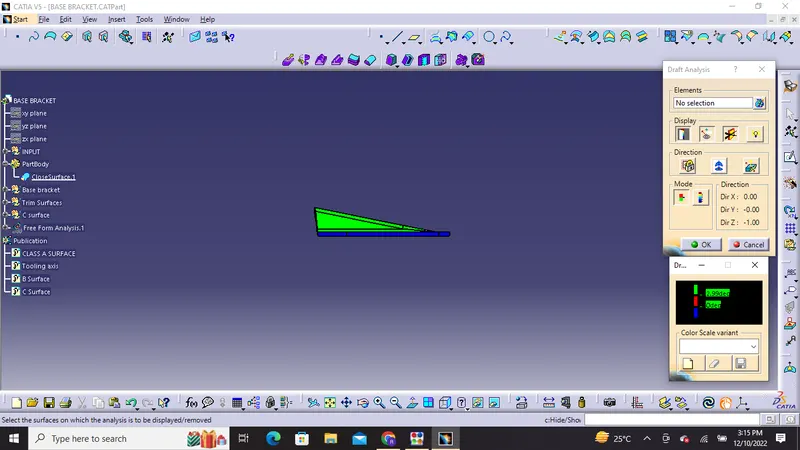
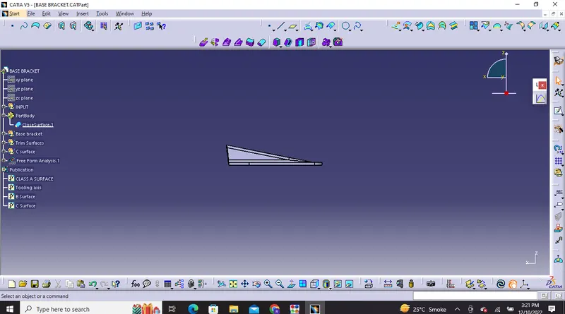
4) TOP VIEW
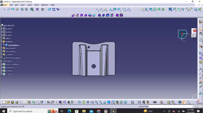
Tree structure with surface geometries,part body and publications:
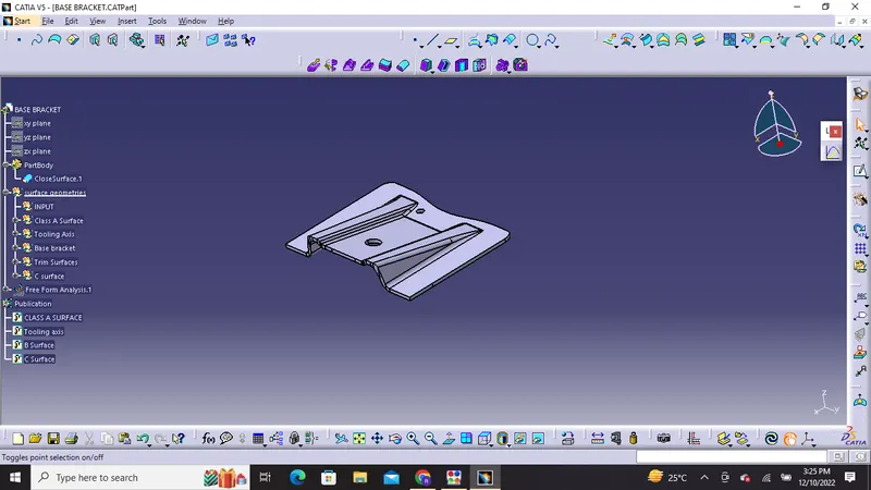
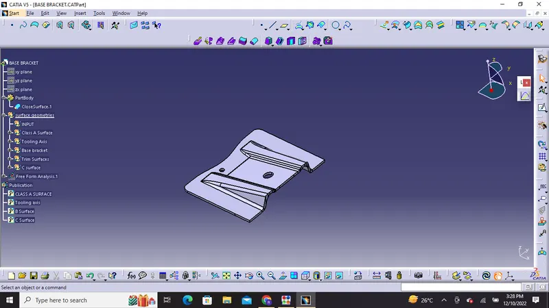
Final solid body with closed surface: