Wiring harness design in CATIA V5 - 3D modeling Week 5 & 6 Challenge
AIM : Using the following connectors route the harness layout in electrical workbench and make assembly Harness A & Harness B in CATIA V5.
OBJECTIVE : Objective of this project is to first download the given file from the given link and define all of them as an electrical and give all the required electrical properties to harness assembly product file and then using the electrical harness assembly, route the harness layout of Harnes A & Harness B in CATIA V5. And add annotation to all connectors. Generate CATPart file of harness assembly and convert it in igs.file.
GIVEN DATA :
Harness A consist 5 connectors
- c-1-174357-2-e-3d8
- c-dt04-08sa-c017-99-3d
- c-dt06-08sa-ce01-99-3d
- c-dt06-08sa-ep07-99-3d
- c-ydts26f15-35snv001-99-3d
Harness B consist 5 connector also
- c-dt06-3s-cp01-99-3d
- c-dt06-08sa-ce04-3d
- c-dt06-08sa-ce13-99-3d
- c-dt06-08sa-ep07-99-3d
- c-ydts26f15-35snv001-99-3d
These are the following steps required to do this project.
- Import all the 3D file in catia v5 workbench
- Create a product file for Harness A.
- Define all of them as a geometrical parameter individually
- And then define all as an electrical
- Create an harness assembly for routing
- Select the electrical harness assembly workbench
- Define as geometrical bundle
- Add multibanchable document library
- Define branch for routing
- And then route ( and ) connector harness assembly
- Add branch point on wring harness routing
- Route the branch connector
- Add annotation to all connectors.
- Save the all data
- Now do same process for Harness B connector assembly file
- And make assembly of both Harness A and Harness B assembled file
- Check bundle warning for assembled product
- And last make CATPart file and convert into .igs file format.
HARNESS A
STEP 1 :
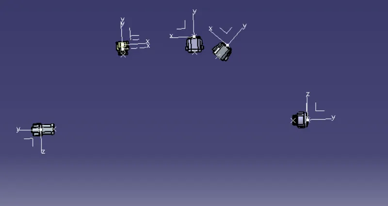
Figure 1: Import all the connectors in Catia v5 workbench
STEP 2 : Define geometric parameter and electrical properties
Figure 2: Connector-DT04-08SA-C017, Define geometric parameter and electrical properties
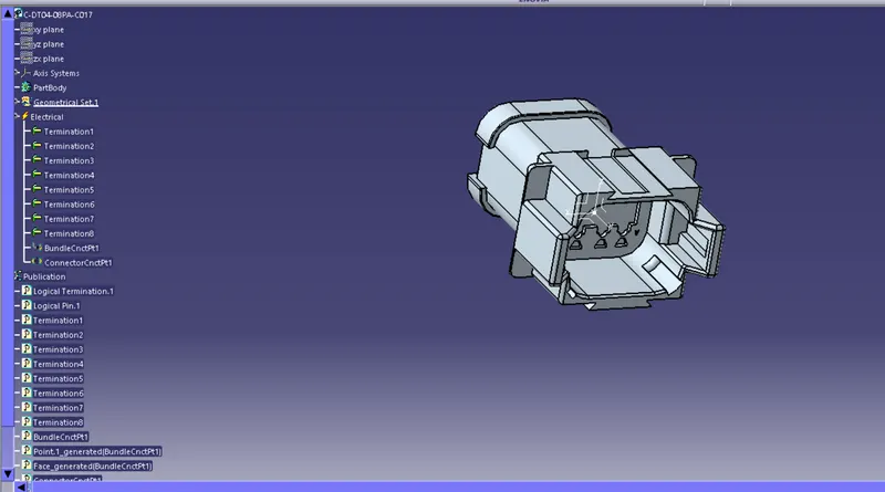
Figure 3: Connector-174357-2, Define geometric parameter and electrical properties
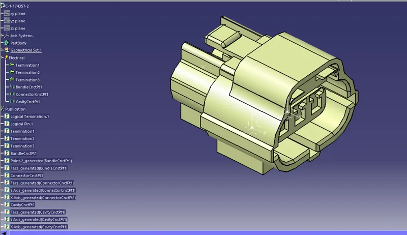
Figure 4: Connector-DT06-08SA-CE01, Define geometric parameter and electrical properties
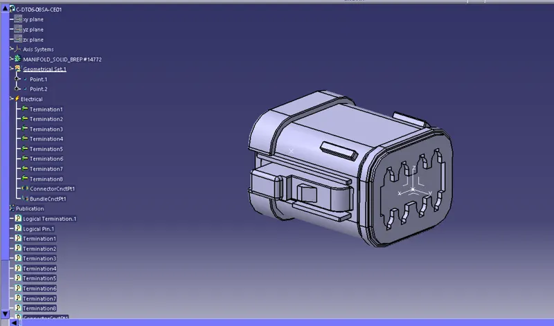
Figure 5: Connector-DT06-08SA-ep07, Define geometric parameter and electrical properties
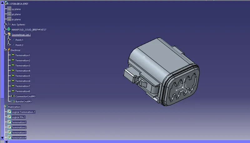
Figure 6: Connector-YDTS26F15-35NV001, Define geometric parameter and electrical properties
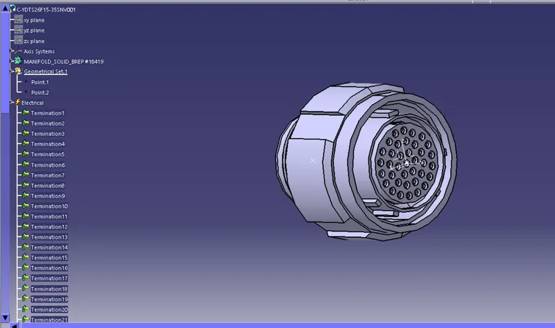
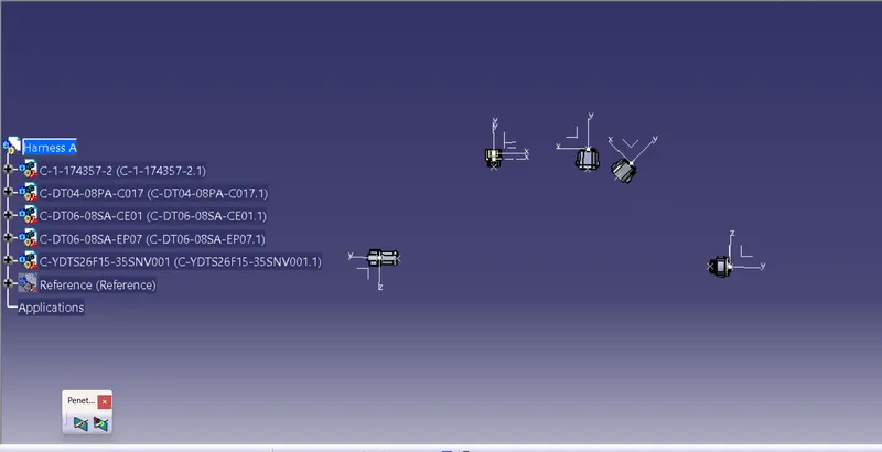
STEP 3 : Create a assembly
Figure 1: Harness A assembly
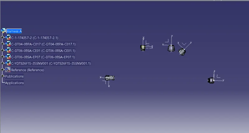
STEP 4 : Now switch to the electrical harness assembly workbench
Figure 1 : Define geometrical bundle
STEP 5 : Select multibranchable document for routing and add branch point on them for another routing
Figure 1 : Routing between DT06-08SA-C017 and YDTS26F15-35SNV001
Bundle dia. is 10mm.
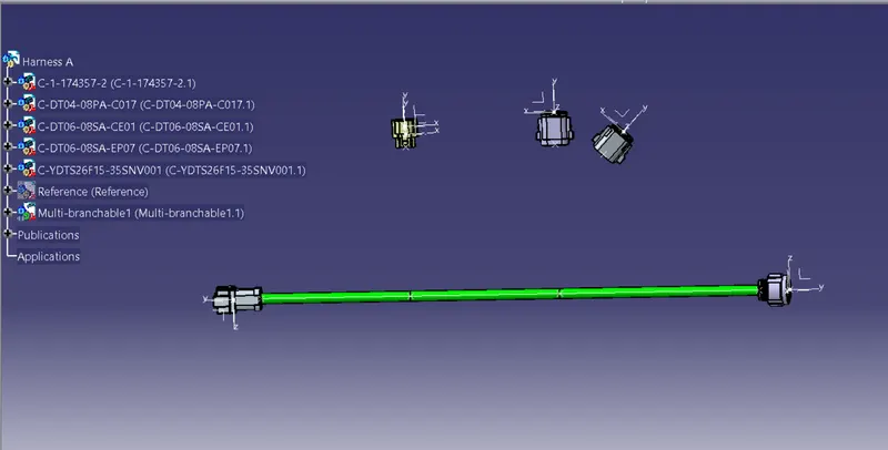
Figure 2 : After adding branch point on routing harness, route the other harness too
Branch bundle dia. is 5mm.
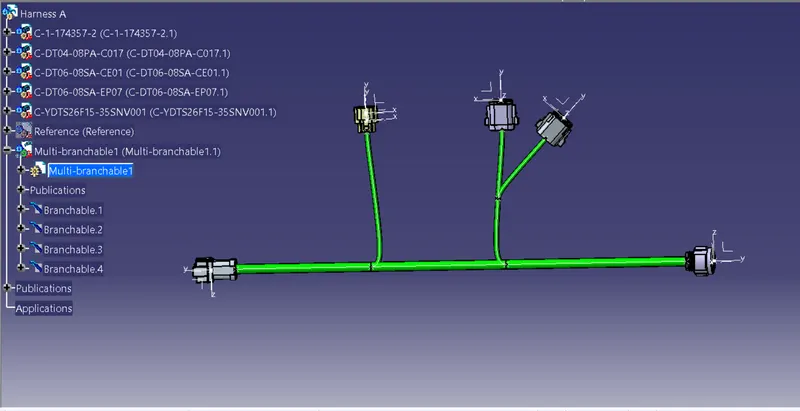
STEP 6 : Annotate connectors
- Go to the assembly design workbench
- Select view creation command ( view as desired plane)
- Select flagnote with ladder (write command)
- And then text (write note)
Figure 1 : Add annotation to connector
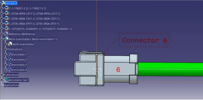
Figure 2 : Add annotation to all connectors
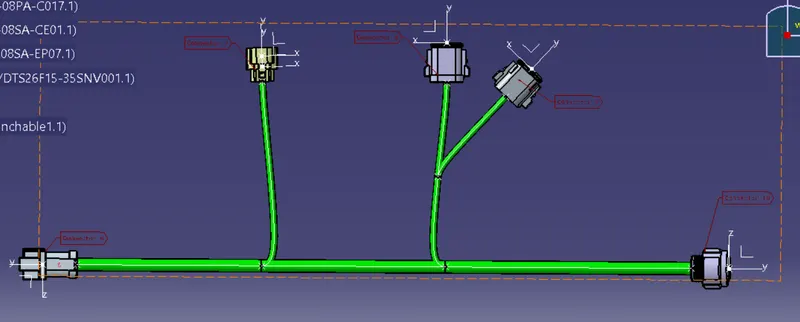
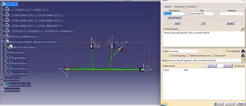
STEP 7 : Check Bundle continuity ( EDIT>SEARCH>ADVANCE>ELECTRICAL-BUNDLE SEGMENT-FULLY CONNECTED)
Figure 1: Checking true bundle continuity
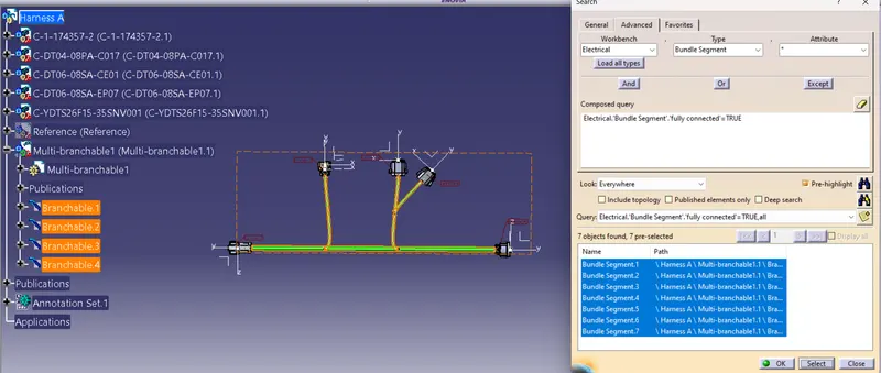
Figure 2: Cheking fulse bundle continuity
HARNESS B
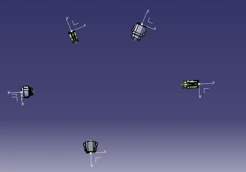
STEP 1 :
Figure 1: Import all the connectors in Catia v5 workbench
STEP 2 : Define geometric parameter and electrical properties
Figure 2: Connector-YDTS26F15-35NV001, Define geometric parameter and electrical properties
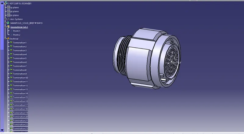
Figure 3: Connector DT06-3S-CP01, Define geometric parameter and electrical properties
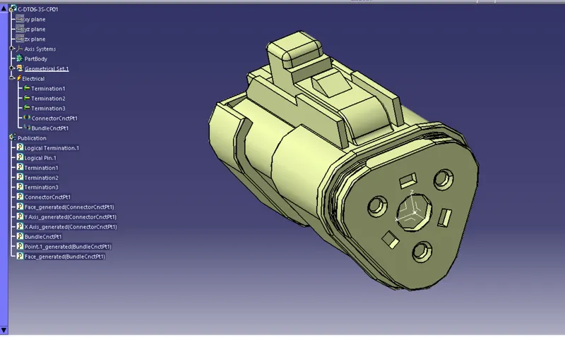
Figure 4: Connector-DT06-08SA-EP07, Define geometric parameter and electrical properties
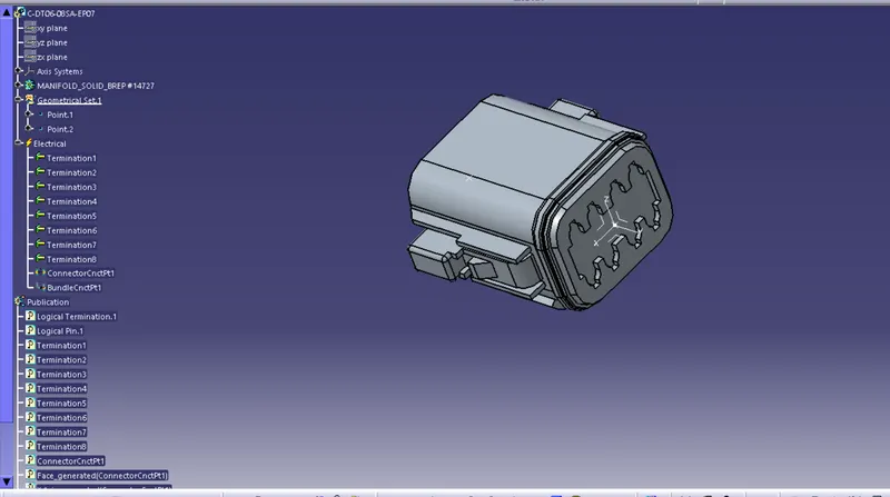
Figure 5: Connector-DT06-08SA-CE04, Define geometric parameter and electrical properties
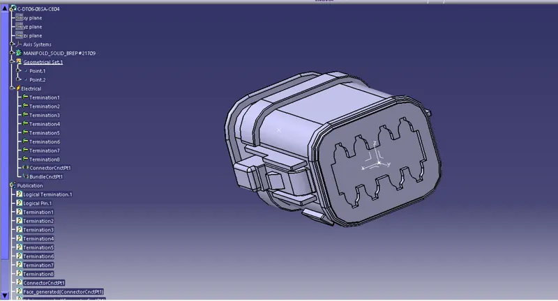
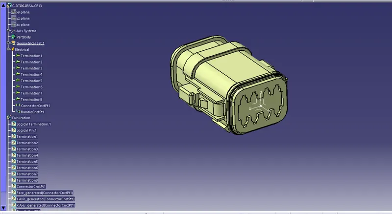
Figure 6: Connector-DT06-08SA-CE13, Define geometric parameter and electrical properties
STEP 3 : Create a assembly
Figure 1: Harness A assembly
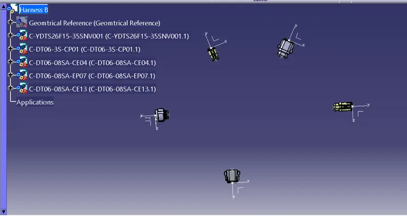
STEP 4 : Now switch to the electrical harness assembly workbench
Figure 1 : Define geometrical bundle
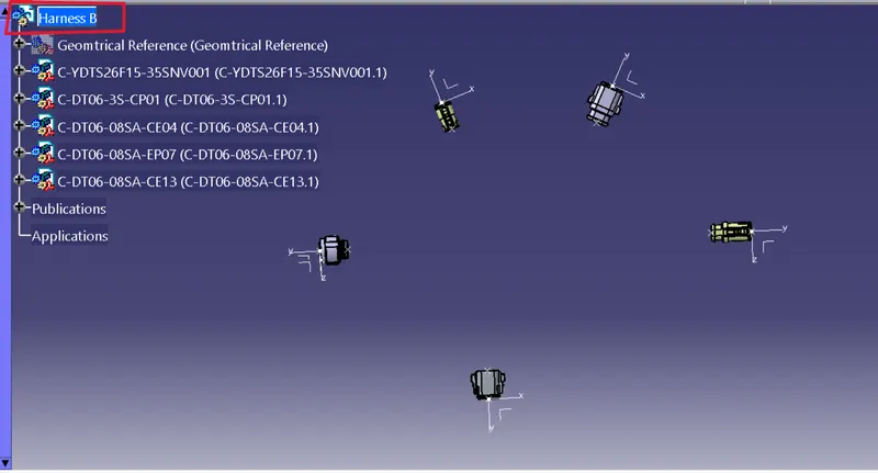
STEP 5 : Select multibranchable document for routing and add branch point on them for another routing
Figure 1 : Routing between DT06-08SA-C017 and YDTS26F15-35SNV001
Bundle dia is 10mm.
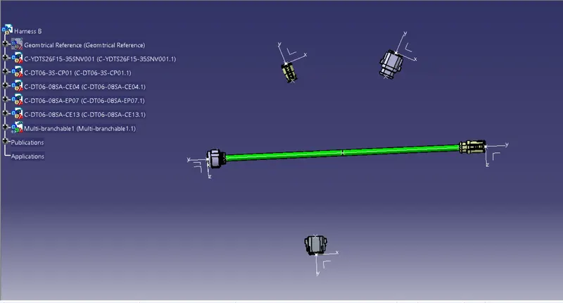
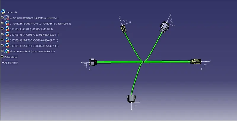
Figure 2 : After adding branch point on routing harness, route the other harness too
Branch bundle dia. is 5mm.
STEP 6 : Annotate connectors
- Go to the assembly design workbench
- Select view creation command ( view as desired plane)
- Select flagnote with ladder (write command)
- And then text (write note)
Figure 1 : Add annotation to connector
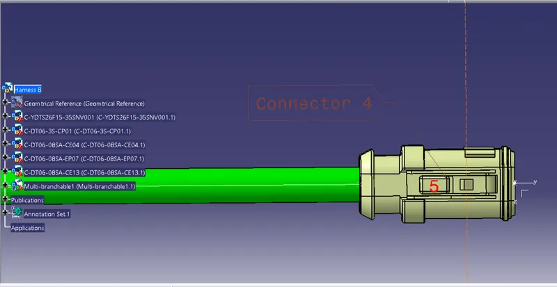
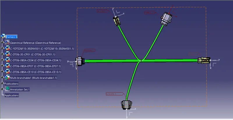
Figure 2 : Add annotation to all connectors
STEP 7 : Check Bundle continuity ( EDIT>SEARCH>ADVANCE>ELECTRICAL-BUNDLE SEGMENT-FULLY CONNECTED)
Figure 1: Checking true bundle continuity
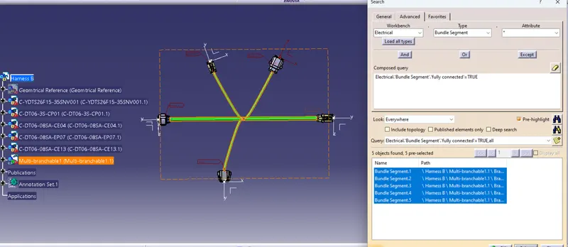
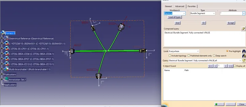
Figure 2: Cheking fulse bundle continuity
For making connection between Harness A and Harness B
- First we have to assembled both the harness in another product file
- By the copy-paste method both harness bring in new product file
- And then switch to the electrical harness design workbench to connect electrically
Figure 1: New product file (HARNESS A&B ASSEMBLY) and bring both harness A & B into that new product file
Figure 2: Switch to the electrical harness design workbench and make connection between A abd B. (you can see that constraints are being added and electrical connection is done between two harness)
Figure 3: Full electrical connection between both harness
Figure 4: Here you can also see bundle continuity is fully perfact (TRUE)
These are the steps required to generate CAT.Part from product file and convert it in .igs file
- Switch to the mechanical assembly design workbench
- Go to the "tools" command ribbon
- Select "Generate CAT.Part from Product file"
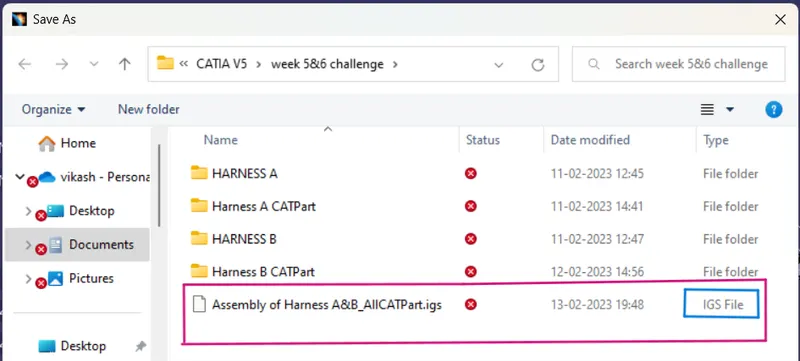
- And for .igs file
- Go to the "File"
- Select "save as"
- And type the file name and
- Click on "save as type" and change CAT.Part to .igs file
Figure 1: CAT.Part from Product file
Here we can see the product tree file convert into CAT.Part file
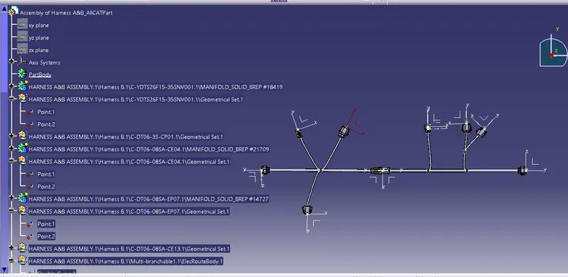
Figure 2: Here we can see that Cat.part is converted into .igs file

CONCLUSION
Here we route the Harness A and Harness B and then make assembly of both harness. Diameter of main bundle is 10mm and branch bundle is 5 mm. Add annotate to all connectors then check the bundle continuity. After that, change the product file into CAT.Part and make that CAT.Part in .igs file.