Project - Speed Control of a Direct Current (DC) motor
PROJECT - Speed Control of a Direct Current (DC) motor
AIM - To model a DC motor to maintain a desired speed for the motor.
OBJECTIVE - The objective of the model is to find maintain angular velocity of the motor. Input - supply Voltage (Vs). Output - Angular velocity (theta_dot).
Mathematical modeling
Input - supply Voltage (Vs). Output - Angular velocity (theta_dot).
Torque constant , T = Kt*i Back EMF(Vb) = Km*theta_dot where Km & Kt= Back emf and torque constant Vb = voltage speed = Km*theta_dot Theta_dot = angular velocity.
Equation of the DC motor circuit
Electrical CKT ( using KVL) , La*di/dt+Ra*Ia+Vb = Vs La*di/dt+Ra*Ia+ Km*theta_dot = Vs ......eq(1)
Mechanical CKT, J*theta_double_dot + B*theta_dot = Kt*Ia ......eq(2)
Electrical Equation La * di/dt + Ra*Ia - Vs = -Vb = -Km * theta_dot
La* di/dt = Vs - Km * theta_dot - Ra*Ia
di/dt = 1/La ( Vs - Km* theta_dot - Ra*Ia) .........eq(3)
Mechanical Equation
J * d^2 (theta)/dt^2 + B*d(theta)/dt = Kt* Ia
J*d^2(theta)/dt^2 = Kt*Ia - B*d(theta)/dt
d^2 (theta) / dt^2 = 1/J (Kt*Ia - B*d(theta)/dt) .........eq(4)
Electrical modeling System
Change eq(1) and eq(2) into Laplace transformation
(La*s +Ra)Ia(s) + K*s*theta(s) = V(s) and s(J*s +B)*theta(s) = K*Ia(s) The transfer function in term of position and velocity.
Now we have to Model the design (simulink based modeling)
this model, model through equation (3) and eq(4)
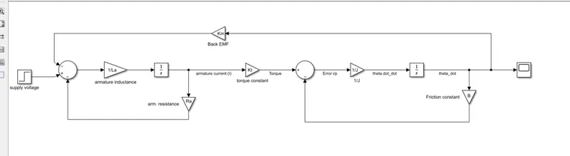
BLOCK usage:
- Step block
- sum block
- gain block
- integrator
- Scope block
Connection of the Model
- First shortout all the required simulink blocks. The required block are step , sum , gain , integrator and scope block.
- First connect Electrical ckt equation(3), as we see ther are 2 negative and 1 positive sign so we take a sum block and give input into it.
- Positive sign connect with a step block.
- A gain armature inductance connect with output of the sum block.
- After that integrator block connect with gain armature resistance.
- Now we have to connect a mechanical CKT , 2 sign available ( +,-) , so we take a sum block and connect with a gain inversly multiple moment of inertia .
- A integrator connect with a viscous friction constant block.
- gain torque constant block connect with a output armature current input.
- and a back EMF block connect with a angular velocity
- last, scope block connect with a output of the angular velocity.
Explanation of the connection
A step block which give supply voltage as a input after that the connection between integrator and armature resistance to give us a voltage across resistance. A gain inversly inductance connection give us a output of the whole electrical CKT. And a integral gain inductance give us a armature current.Torque multiply with armature current gives torque. From the eq(4) torque minus viscous friction give us angular velocity as we wanted.
Control law design and test
setling time must be less than 2 second Overshoot must be less than 5 percent Steady state error should be less than 1 percent
Standard Parameter taken
J = 0.01; % moment of inertia of the rotor in Kgm^2
B = 0.1; % motor viscous friction constant iin Nms
Km= 0.01; % back emf constant in V/rad.s
Kt = 0.01; % motor torque constant in Nm/amp.
Ra = 1.0; % Ra armature resistance in ohm
La = 0.5; % La armature inductance in henry.
Step block set to be [ 1] [0] [1] means step size, initial value and final value.
Model setting we select start time = 0.0 , final time = 10.0
solver selection , Type ( Fixed step) and solver ( ode4- runge kutta)
solver detail , Fixed step size is 0.01
Response of the model Angular response of the DC motor, when we give 1 volt suppy so it respond 0.1 rad/s angular velocity.
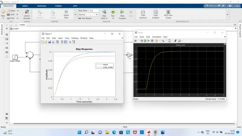
Now we have to test and regulate the PID gains like ( Kp , Ki and Kd)
first regulate Kp upto 96. through #HitANDTrail Method after the Ki & Kd
look the response , as we set to gain 1 rad/s angular speed of DC motor so we have to set first 0.1 to approx 1 in rad/s by the use of Kp( proportional gain).after we set approx 80-85(Kp) above it respond a large overshoot .
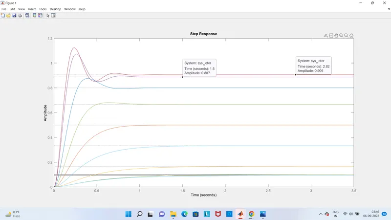
Now after response are overshoot so we need to regulate integral gain and derivative gain to take minimum settle time and too low overshoot condition
Stability of a dynamic system
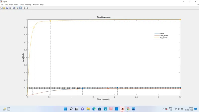
And the response look good, Steady state error almost gone 0.1 to 1 rad/s(as we want angular speed), no overshoot response. Steady state respond better than step(motor) response and unity motor response, settle time taken almost 0.522 sec as compare to motor taking 2.07 sec, unity_motor taking 1.85 sec. Also error better than previously lies on 0.1 sec.
conclusion
So by the help of PID controller we model a very efficient response. minimum settle time less than 2 sec, overshoot response almost behaves like critical damped and very low steady-state error(<1%).