Wiring harness design in CATIA V5 - 3D modeling Week 5 & 6 Challenge
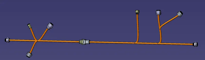
In this challenge we have to create harness A and harness B separately as two geometrical bundles and later interconnect them using the electrical assembly workbench. The layout of both harness A and harness B are shown in the image given below.
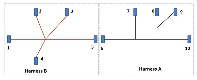
All the connectives in both harness A&B are downloaded add converter to electrical but by following the below steps.
- Download the part.
- Save the part as cat part.
- Switch to mechanical part design
- define the points and the coordinate systems.
- Switch to electrical part design.
- Define the part as an electrical component(connector)
- define the connector connection point and the bundle entry point.
- Create a new catalogue the name of connector.
- Add the connector part into the connector catalog.
All the connectors are defined in the above mentioned way. Then a new assembly started the name of harness A and the connectors 6 to 10 are imported into the assembly.
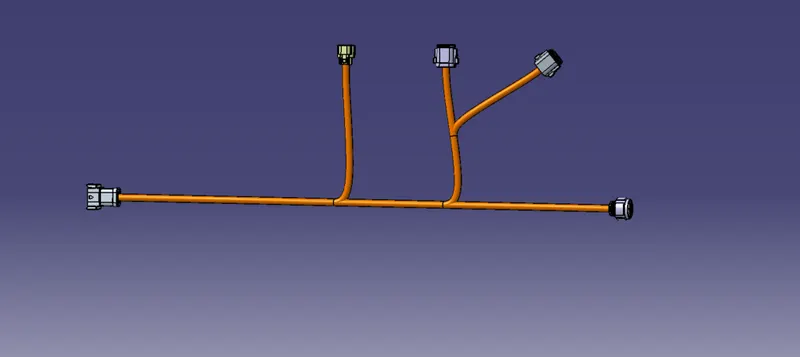
The harness A is created and the screenshot of the 3D model is shown in the image given below.
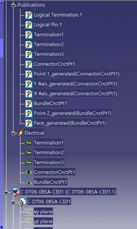
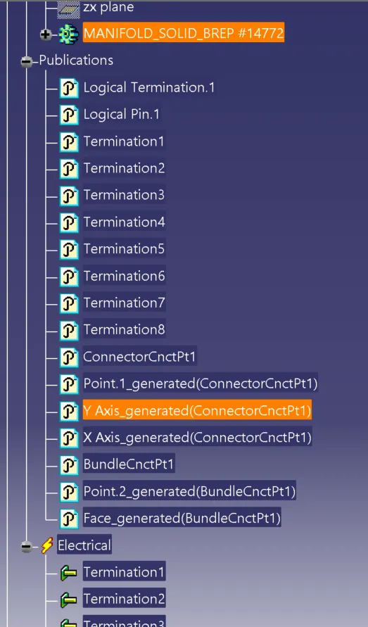
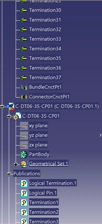
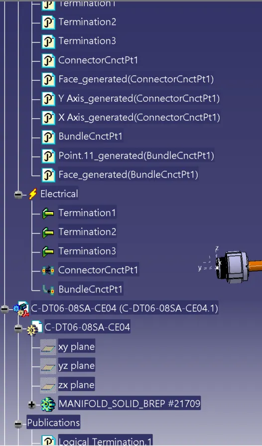
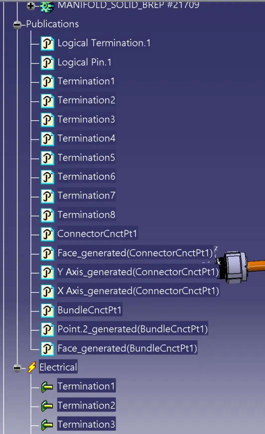
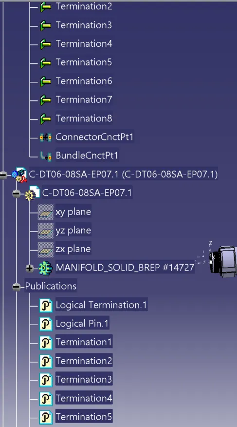
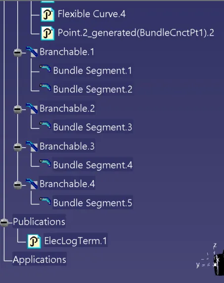
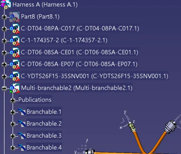
The tree image after harness A is also given below.
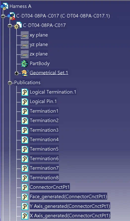
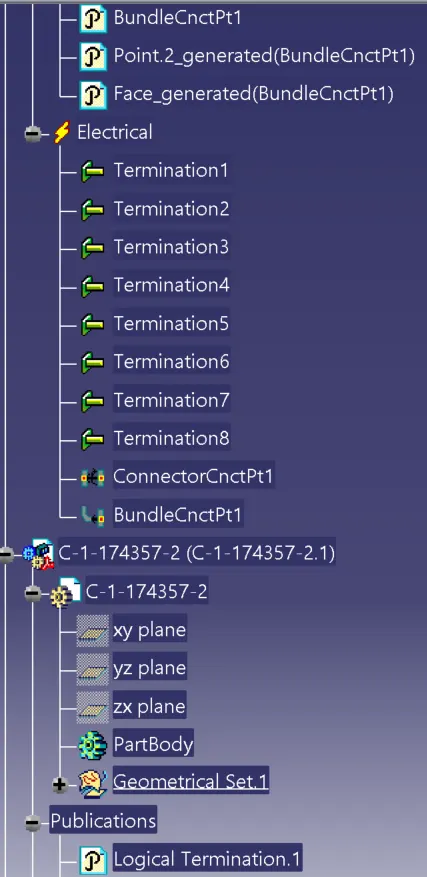
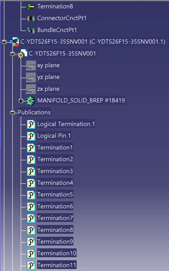
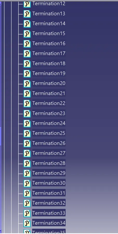
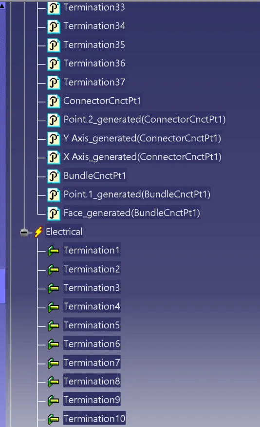
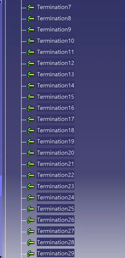
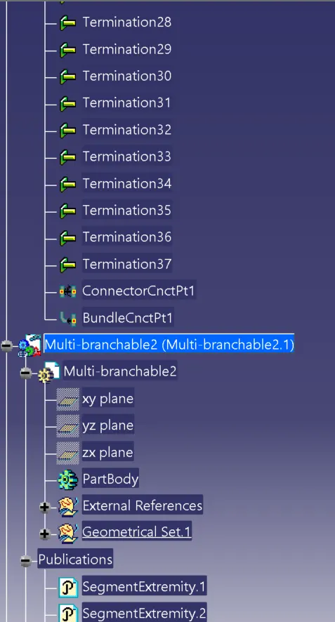
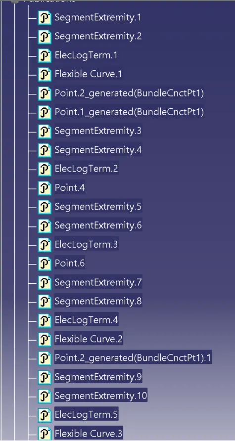
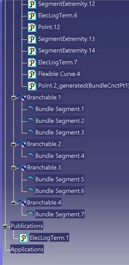
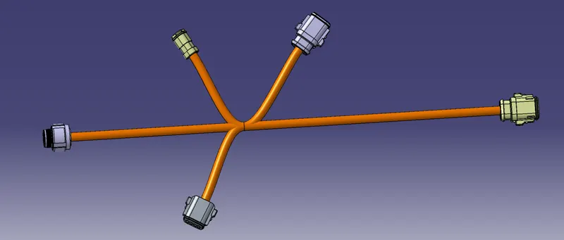
Harness B is created as a separate assembly and the screenshot of the 3D model is shown in the image given below.
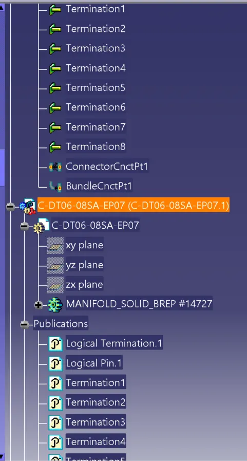
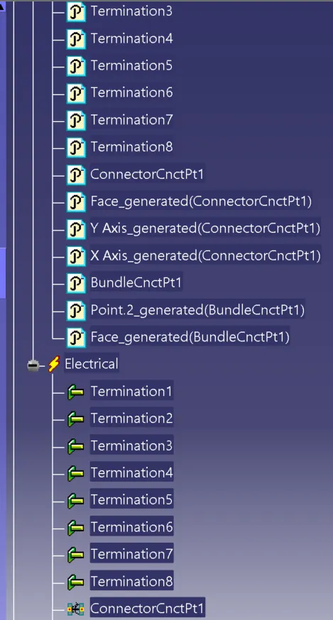
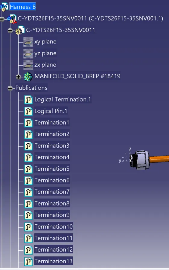
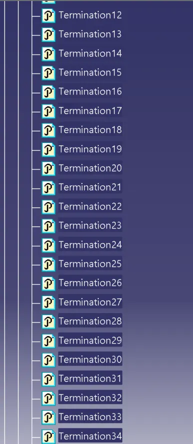
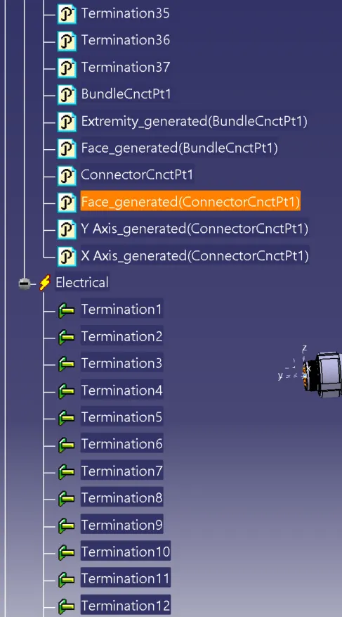
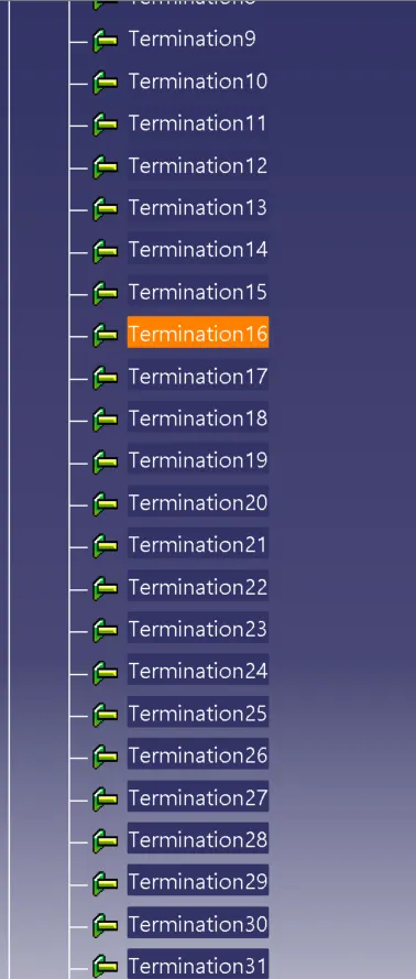
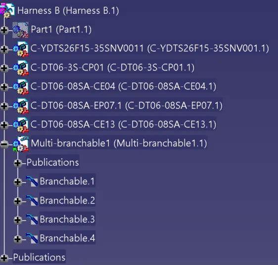
Screenshot of the three images for harness B is also given below.
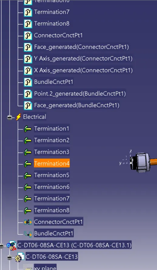
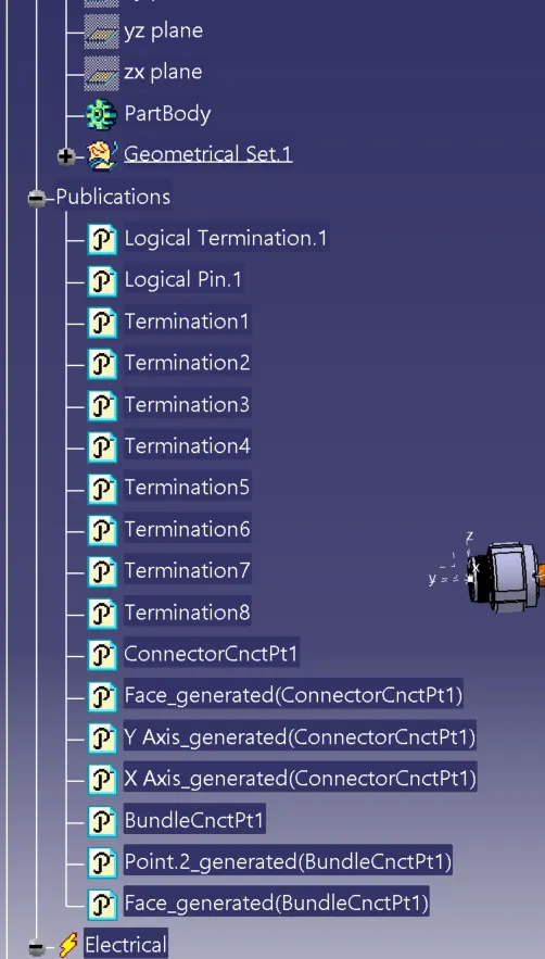
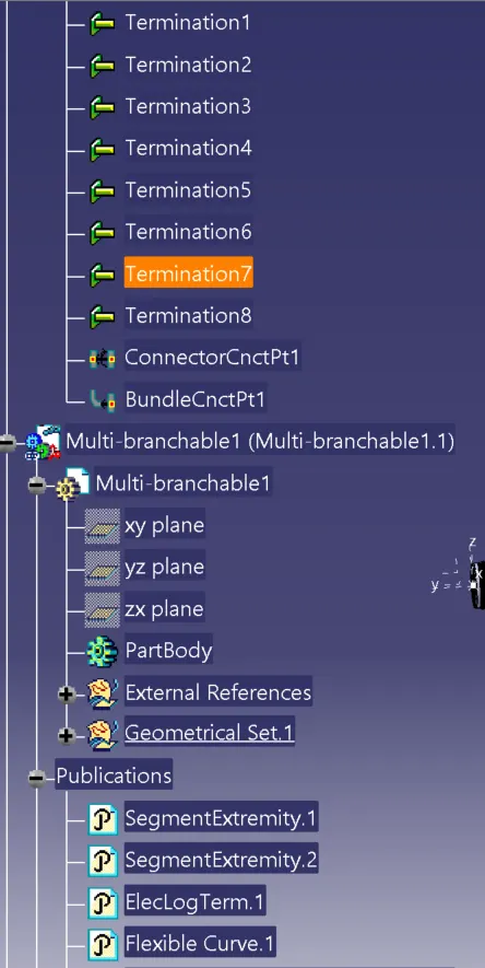
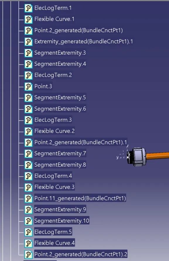
Now interconnection of harness A&B is done.
In order to interconnect 2 wiring harnesses we have to start a new product file and import the harness a and harness B as sub level products.
Now switch the assembly electrical assembly design workbench.
Here we have to use the connect electrical devices tool to connect the connectors five and six together. The whole interconnection is shown in the image below.
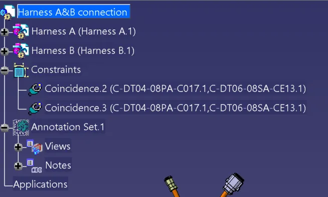
The tree image of the interconnection is also shown below.
Q1
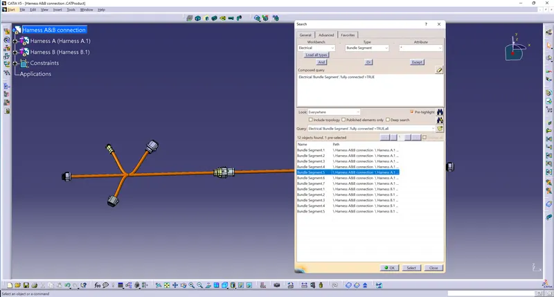
After creating the interconnection between harness A and harness B we have to check the bundle continuity. In order to do the bundle continuity check we have to click on the edit tab in CATIA then select search tool.
In the search window that pops up we have to switch to the advanced tab.
Select the workbench as electrical.
Type as bundle segment.
Select the attribute as fully connected.
In the small window that pops up select true.
Now click on the search button so that all the interconnected bundles will be shown as a list.
The result of the bundle continuity check is shown below.
Q2
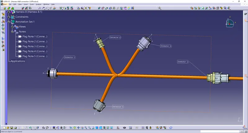
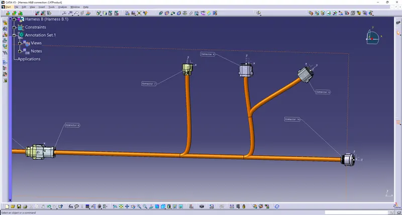
now we have to give annotation to both Harness A and B by switching the workbench to mechanical assembly design.
The annotated images are shown below
Q3
Now in the third question we have to check whether there is any bundle warning that is present. There was no any bundle warnings present and the snap of the bundles are shown below.
Q4
now a Catpart of the whole assembly is created
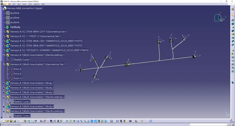
the Catpart is then converted into IGES and .stp formats.