Wiring harness design in CATIA V5 - 3D modeling Week 5 & 6 Challenge
Wiring harness design in CATIA V5 - 3D modeling
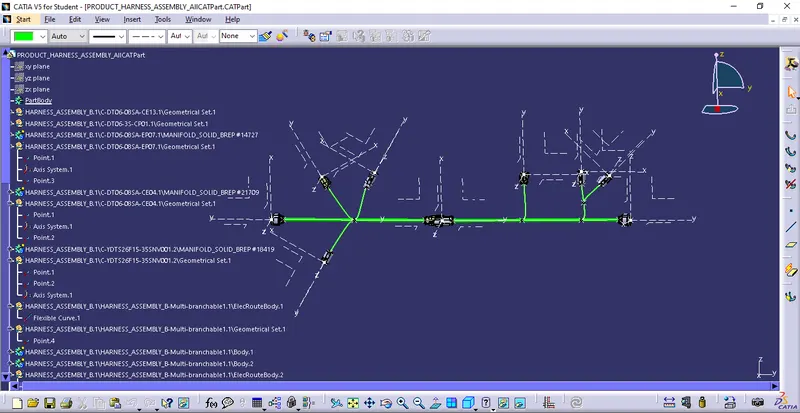
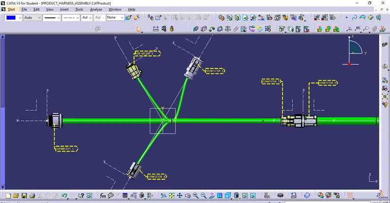
Q1. Route the following harness layout in the Electrical workbench. Make assumptions for harness bundle diameters. Use the connectors provided. After completion of routing,
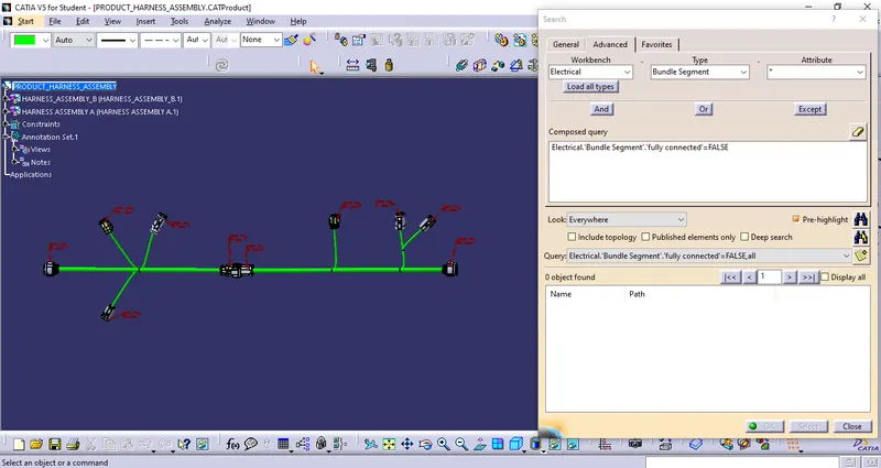
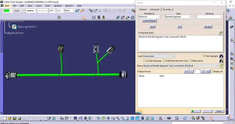
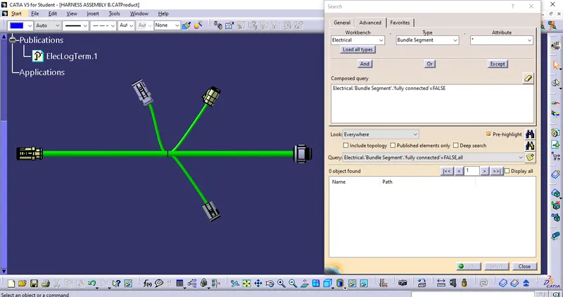
- Check the bundle Continuity. Add a snap of the result in the submission
- Add annotation to all connectors. Make assumptions for annotations like connect 1, 2, etc.
- Check for the bundle warning. Add snap.
- Generate CAT.Part of harness assembly and conversion is in. igs format.
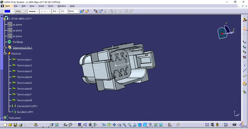
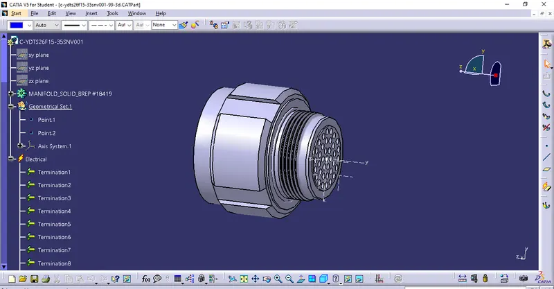
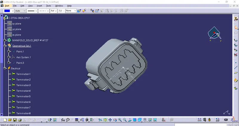
- Connector connection point:
- It is the point at which two mating surfaces of the plug and connector are connected.
- To create such a connector connection point, follow the below steps:
- Switch to part design,
- Create a midpoint on the contact face which will be normal to wire bundle insertion.
- Create Axis System with respect to the point which we have created and define the axis direction as shown below,
- Switch to 'Electric Part Design'
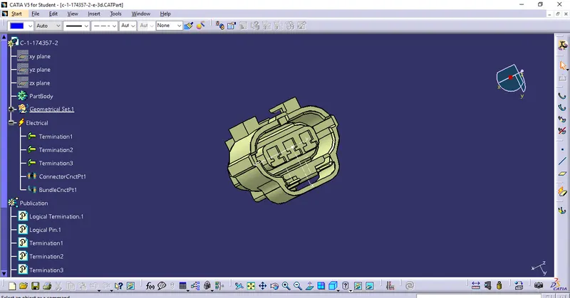
- Define the part as the connector in CATIA V5, and give the no. of termination as needed.
- Define connector connection point.
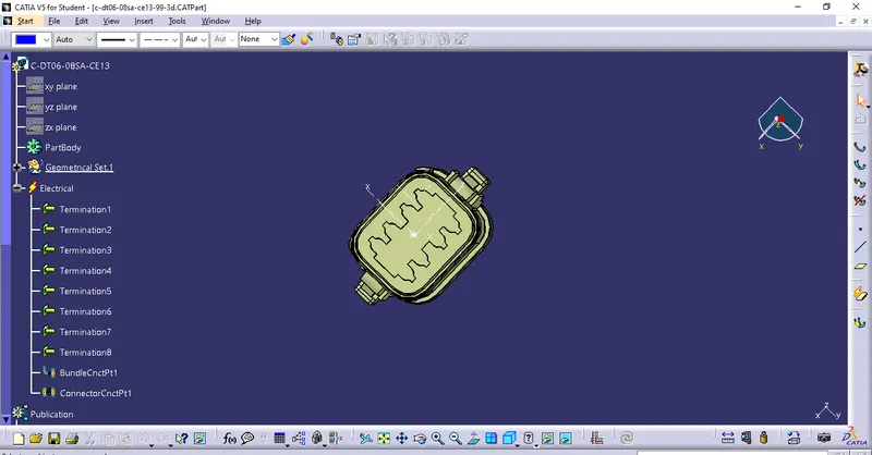
- Bundle connection point:
- The bundle connection point is used to specify the position and the direction of the bundle segment connected to the connector or the equipment.
- To create such a Bundle connection point, follow the below steps:
- Switch to part design,
- Create a midpoint on the contact face which will be normal to wire bundle insertion.
- Switch to 'Electric Part Design'
- Since we had already defined the component as a connector.
- so, Define the Bundle connection point.
- DEFINE THE COMPONENT AS ELECTRICAL TO CREATE ASSEMBLY FOR HARNESS A:
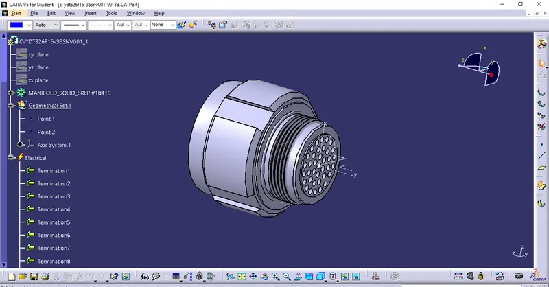
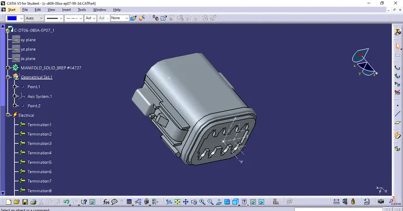
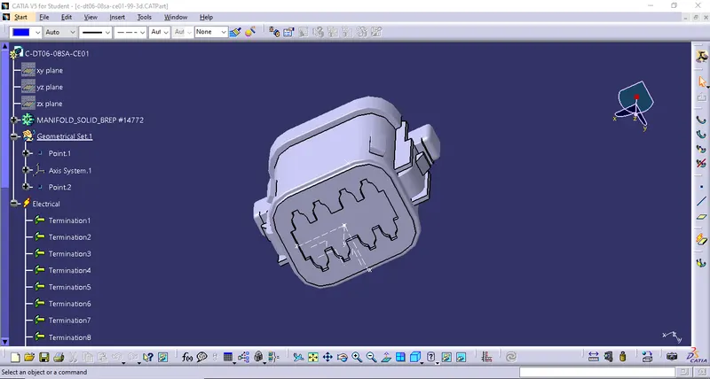
2. DEFINE THE COMPONENT AS ELECTRICAL TO CREATE ASSEMBLY FOR HARNESS B:
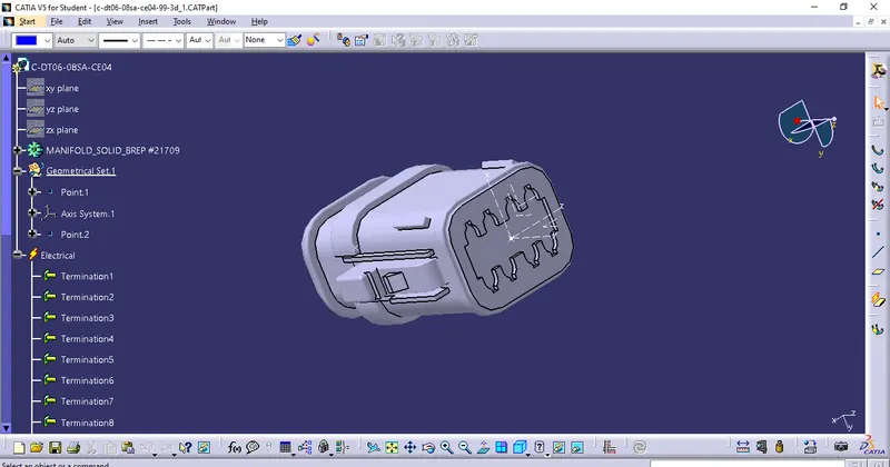
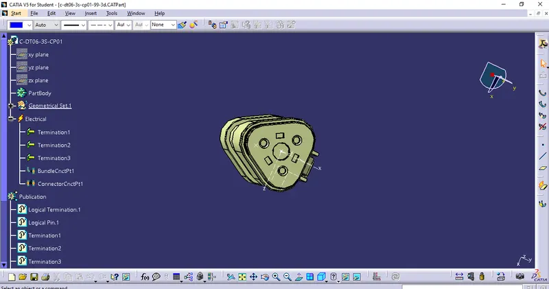
- Adding the annotation to all connectors.
- Switch to assembly part design
- Select the annotation toolbar
- Select view from the reference tool to create the ref. plane.
- After creating the ref. plane select the flag note with the ladder option.
- Annotate the connector.
- Checking the bundle Continuity. Adding the snap of results in the submission
- Go to edit menu
- Select the Search option and in that select the advance option
- set the following option
- electrical
- bundle segment
- fully connected
- provide condition (true/false)
- after providing constrain select highlight option.
- Convert product file to IGS file: