Wiring harness design in CATIA V5 - 3D modeling Week 5 & 6 Challenge
Below is the process of Harness routing.
- Download the required connectors from the given location.
- Make all the connectors as electrical components as below.
- Create required geometrical parameters in part design, like connector connection point and axis, bundle connection point.
- Then move to electrical part design and define the part as 'define connector'.
- Define bundle connection point, connector connection point and cavity connection point.
- Create a new product and make that as electrical product by using 'Geometrical bundle' command in Electrical harness assembly work bench.
- Position all the connectors as per the given harness layout.
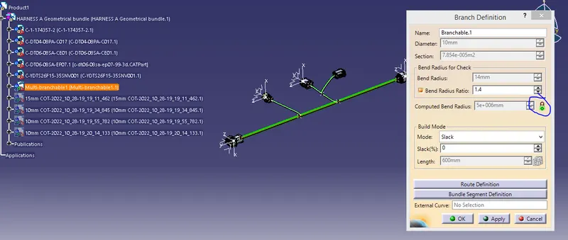
- Use Branch definition command and route the main trunk first.
- Use add branch point to create branches and route them by using route definition with the other connectors.
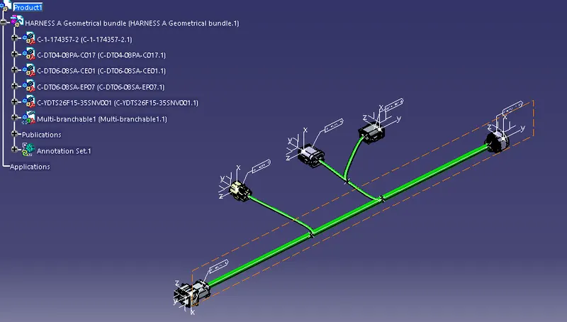
Harness A
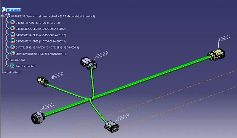
Harness B
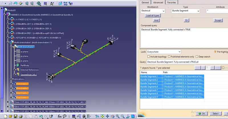
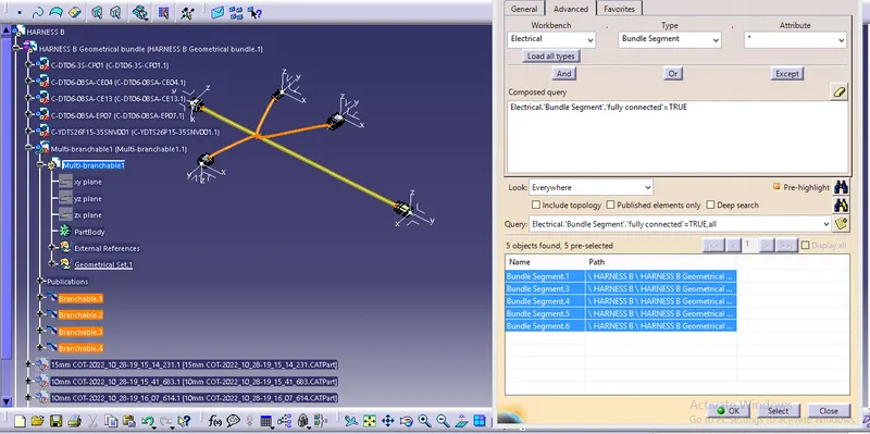
1. Check for bundle continuity and resolve if it is not fully connected.
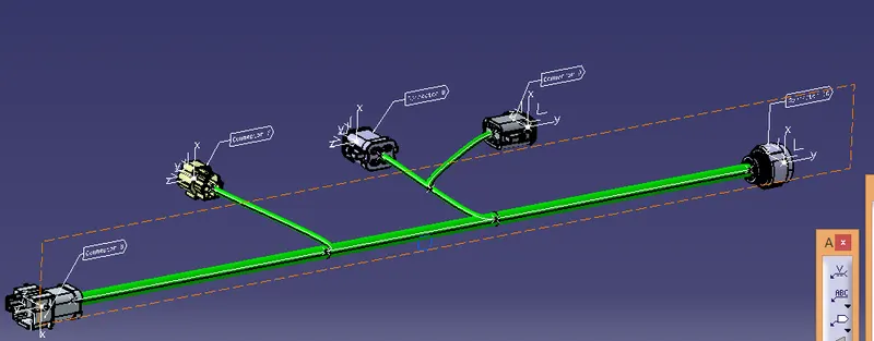
2. Add annotations for all the connectors in Harness A & B.
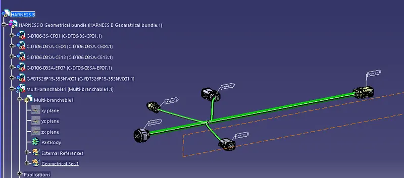
3. Resolve if you have any bundle warnings.