Wiring harness design in CATIA V5 - 3D modeling Week 5 & 6 Challenge
WIRING HARNESS DESIGN 5&6
AIM:
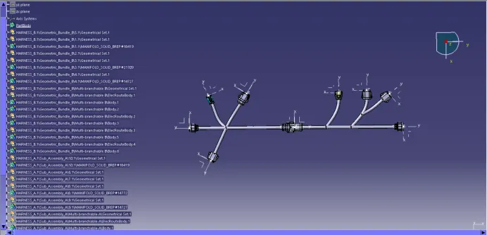
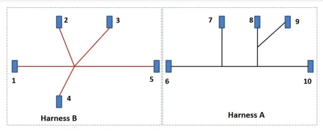
Create a Wiring harness assembly and route the harness per the given layout.
OBJECTIVE:
To electrically define all the parts provided.
Create a wiring harness assembly and route the harness per the given layout.
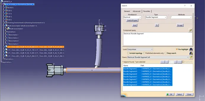
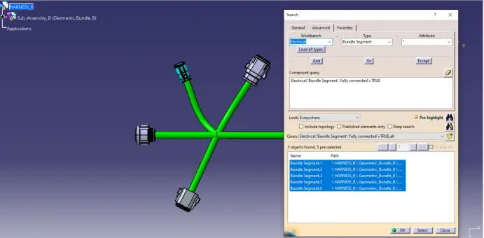
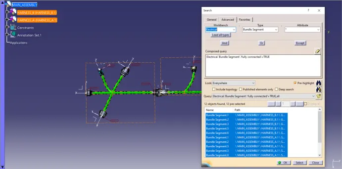
To check for the bundle segment continuity.
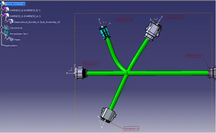
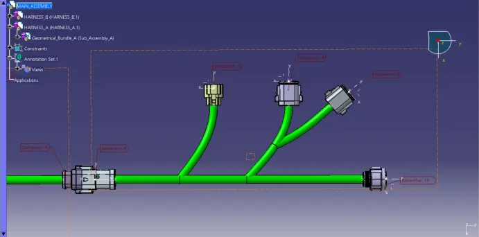
Add annotations to all connectors.
To check for bundle warning.
To generate the CAT.part of the complete wiring harness assembly and convert it into .igs format.
SOLUTION METHODOLOGY:
Step - 1:
Download all the 3-D CAD data required for the above assignment and save it in the desired folder.
Step - 2:
To identify the connector side and the bundle side and create points and axis system at the mid-point of the mating surface.
Step - 3:
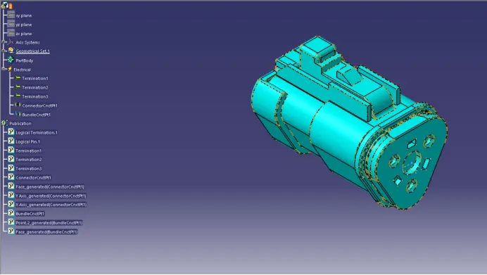
To navigate to the Electrical Part design workbench and define the electrical properties of the connector by:
First defining the part body as a connector.
Then defining the connector connection point.
And then defining the bundle connection point.
The above steps should be followed for all the Connectors to electrically define them and use them in the wiring harness assembly.
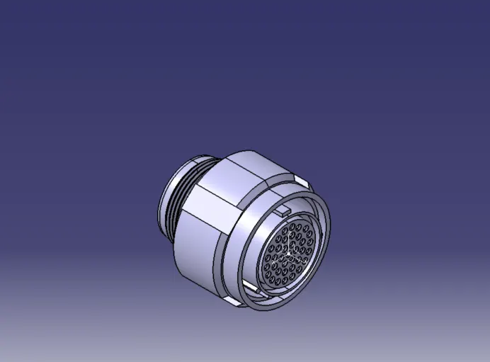
CONNECTOR - 1:
CONNECTOR - 2:
CONNECTOR - 3:
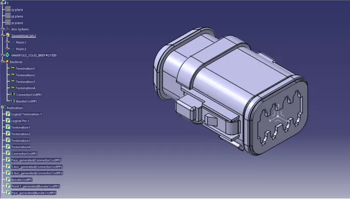
CONNECTOR - 4:
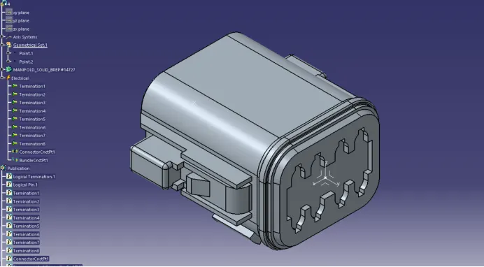
CONNECTOR - 5:
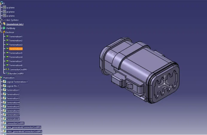
CONNECTOR - 6:
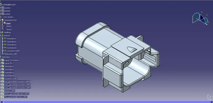
CONNECTOR - 7:
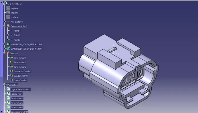
CONNECTOR - 8:
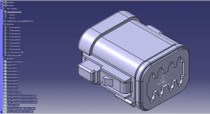
CONNECTOR - 9:
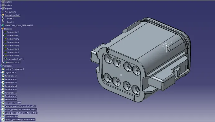
CONNECTOR - 10:
Step - 4:
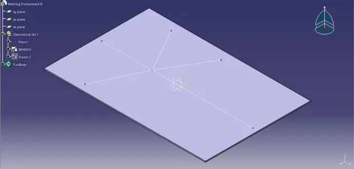
Create a working environment platform to place the connectors easily, smoothly, and in a proper orientation.
WORKING ENVIRONMENT FOR WIRE HARNESS A:
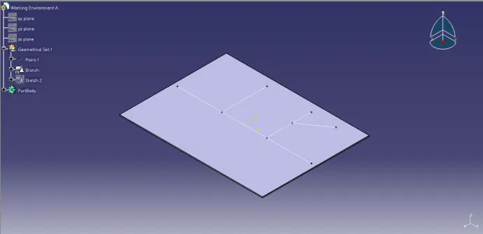
WORKING ENVIRONMENT FOR WIRE HARNESS B:
Step - 5:
Create a new product for Wire harness A layout.
Add all the connectors that are required for the harness layout and also add the working environment.
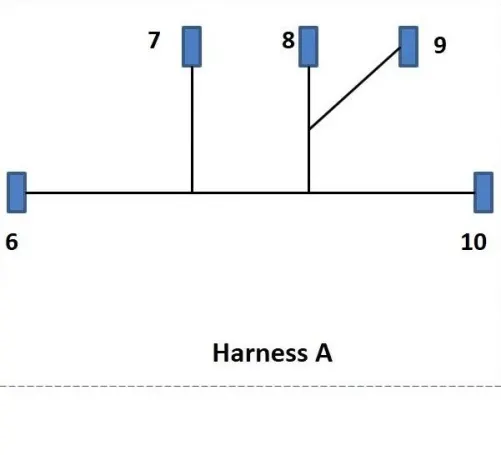
Place all the connectors in their respective positions according to the given layout.
WIRE HARNESS A LAYOUT:
Step - 6:
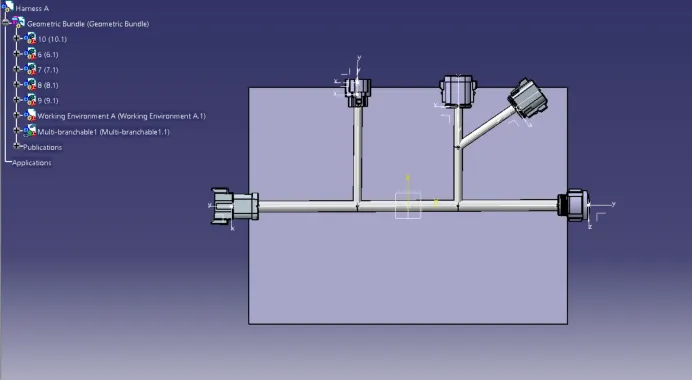
Create the wire routing according to the above layout.
WIRE HARNESS A ROUTING:
Step - 7:
Checking the continuity of the bundle segments:
Step - 8:
Create a new product for the Wire harness B layout.
Add all the connectors that are required for the harness layout and also add the working environment.
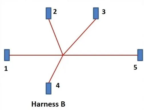
Place all the connectors in their respective positions according to the given layout.
WIRE HARNESS B LAYOUT:
Step - 9:
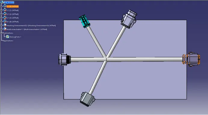
Create the wire routing according to the above layout.
WIRE HARNESS B ROUTING:
Step - 10:
Checking the continuity of the bundle segments:
Step - 11:
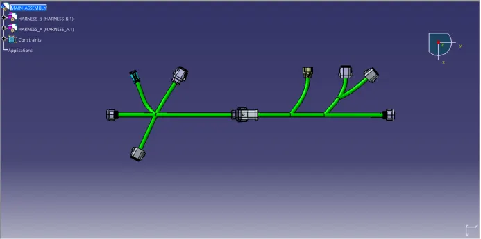
Creating a new product file to assemble both wire harnesses A and B.
Add both the Wire harness A and Wire harness B product files to the main Wire harness assembly file.
Step - 12:
Navigate to the Electrical Assembly Design workbench.
Select the 'connect electrical devices and select connector 5 of wire harness B and connector 6 of wire harness A.
ADDING ANNOTATIONS TO ALL CONNECTORS:
CHECKING FOR BUNDLE CONTINUITY:
GENERATING THE CAT.PART OF THE WIRING HARNESS ASSEMBLY AND CONVERTING INTO .IGS FORMAT: