Advanced Sheet Metal Design Using NX Cad Challenge_2_Box Assembly
To Create Box Assembly in NXCAD
- Aim - To design Box Assembly in Siemens NXCAD sheetmetal application.
- Objective - To learn sheet metal designing and design a sheetmetal box assembly in Siemens NX CAD.
- Introduction - Sheet Metal is metal formed by an industrial process into thin, flat pieces Sheetmetal is a comprehensive cold working process for metal sheets usually below 6mm, including shearing, punching/cutting/folding, and riveting, splicing, etc.
- Sheetmetal is one of the fundamental forms used in metalworking and it can be cut and bent into a variety of shapes. Countless everyday objects are fabricated from sheetmetal. Thickness can vary significantly; extremely thin sheets are considered foil or leaf, and pieces thicker than 6mm are considered plate steel or structured steel.
- Sheetmetal box assembly consists of the main box cover, and the hinge made out of sheetmetal itself. All parts are designed using the sheetmetal features as presented.
- Design Methodology -
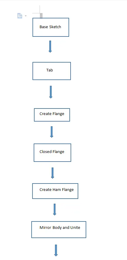
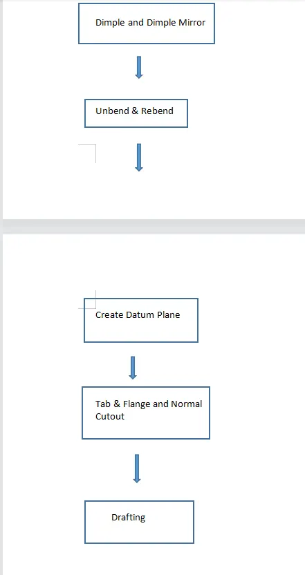
- Description - In the design process of the box assembly, various features have been repeated and are used in different parts. All of them are described in the order followed in the design process.
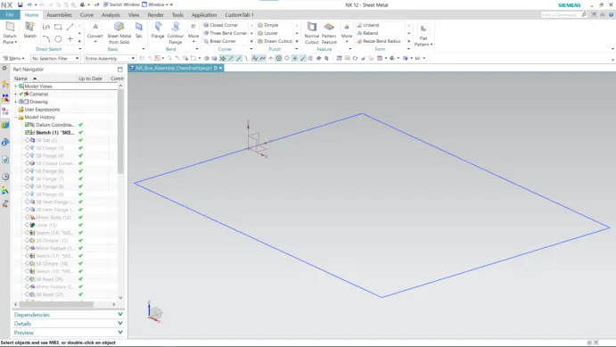
- Sketch for base tab -
For the box assembly, a sketch for the tab is created in the XY plane first.
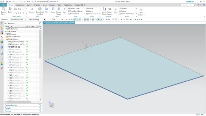
- Tab Feature - A tab is created after a sketch is created in any of the planes or datum planes created. The tab is always the parent feature for other features following it. In the box assembly, the tab is created after a 2d sketch in the XY plane.
The constant thickness of sheetmetal base has been adjusted in the preference setting already to 1mm.
- Flange Feature - The Flange feature adds a flat flange at an angle to the planar face and adds a bend between the two. While creating a flange we have to set different parameters such as the length of the flange, its angle, length reference (inside, outside, or web), and inset (Material inside, Material outside, or bent outside). Other parameters like bend radius, bend relief, and Neutral factor are also needed to be considered.
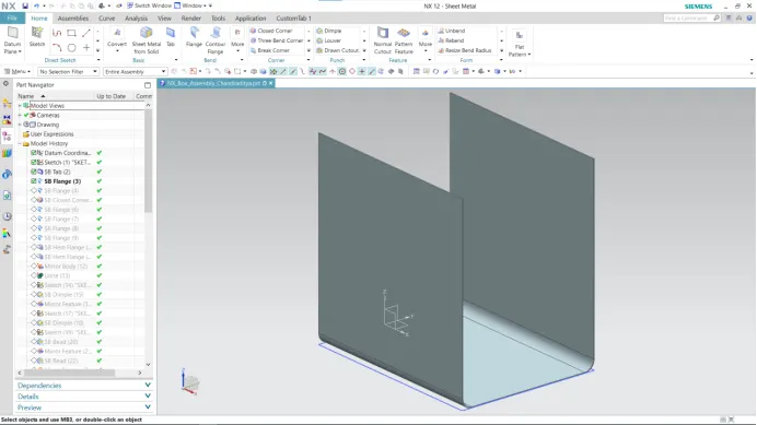
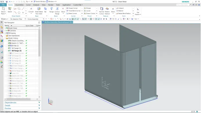
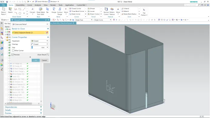
- Closed Corner - This tool closes the opening between two flanges or between the tab and flange which are perpendicular or at any angle. If should be adjacent to be able to apply the feature. It results in a closed part following the shape of the other part. For this box, a closed corner is used on both sides of the bottom of the flanges normal to the XZ plane.
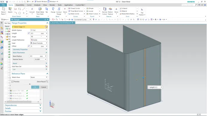
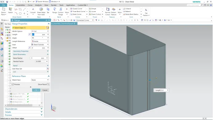
- Flange for fastening - For the fastening purpose by the bending of edges, a flange zero length is first made and another bend flange is used to bend it outwards to obtain the following result.
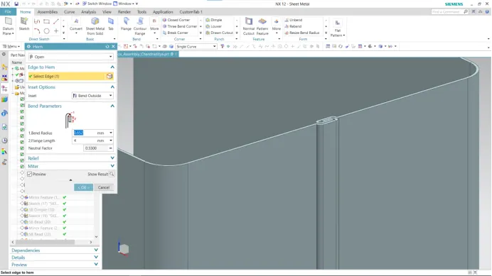
- Hem Flange - Hem flange is the feature that bends the open edges at the end and prevents the sharpness of the sheet metal from any possible accidents. Also, it increases the strength and stiffness of the sheet metal part.
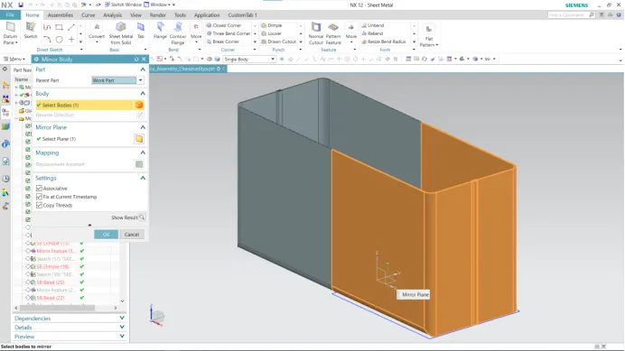
- Mirror Body - Mirror body features allow a solid body to get copied and mirrored with respect to a plane. Here, the design is mirrored across the YZ plane.
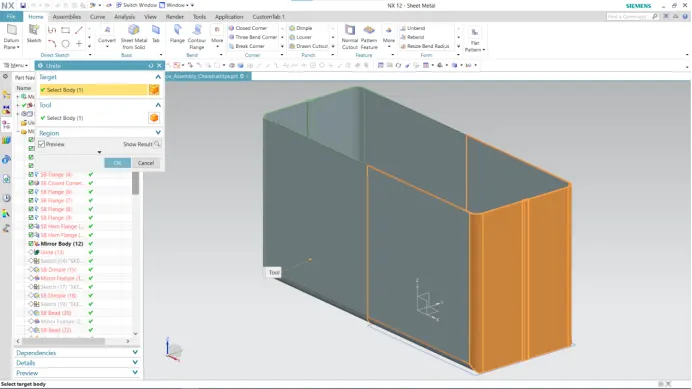
- Unite - After the mirror operation is completed Unite feature is applied to Unite the solid bodies created after in mirror operation.
- Dimple - This feature is used to lift an area of the model inside a sketch that simulates a stamping tool. The Dimple command makes an indentation in the sheetmetal part, using a sketched section as its outline.
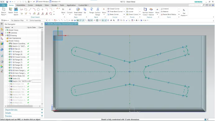
- Sketch of the Dimple Feature -
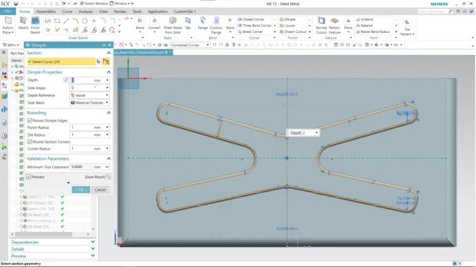
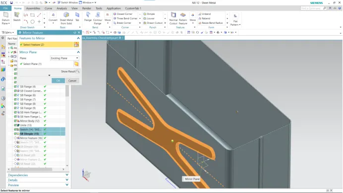
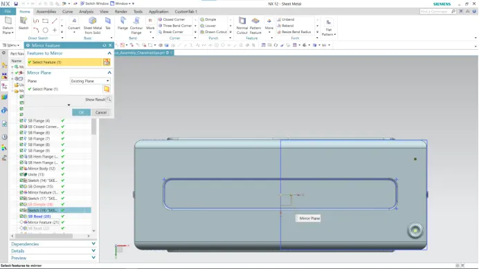
- Mirror Feature - Now the dimple feature is mirrored across the XZ plane.
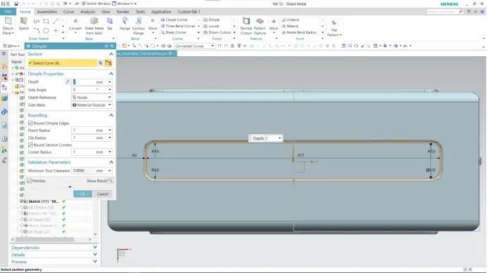
- Dimple - Dimples are created in the bottom of the Box assembly to provide more strength and rigidity to the flat structure of the component.
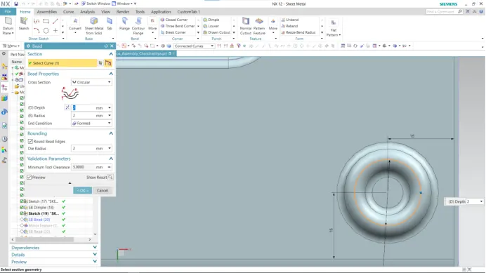
- Bead - The bead is like a raised rib in the sheetmetal panel. It requires that you have at least one sheet metal panel in the active part as well as an open or closed-loop sketch.
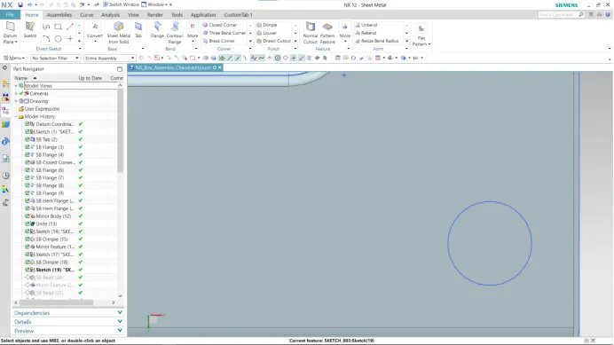
- Bead Operation is performed -
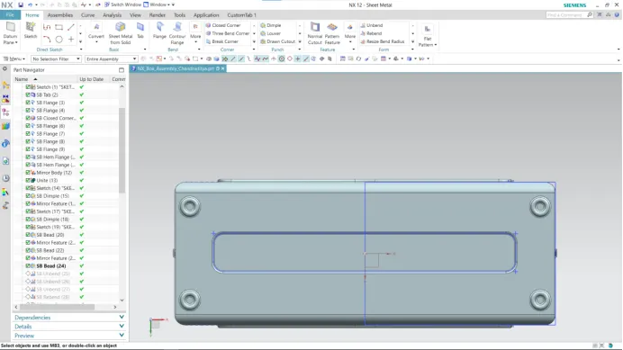
- Bead is mirrored -
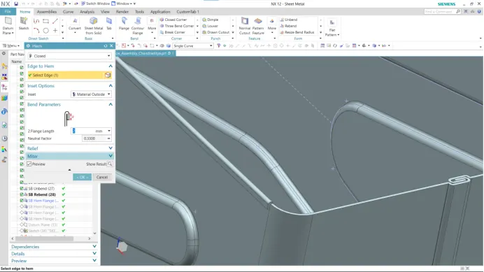
- Hem Flange - At this stage, the hem flange is applied at the top edge of the side flange, and the flanges normal to the YZ plane.
- Datum Plane - Datum Plans are used as a reference on a part where a reference does not already exist. Here the datum plane is created with the reference XY plane. From the plane, it is located at a 203 mm distance.
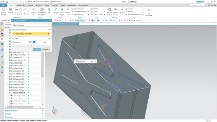
- Lid Creation - To create the lid for the box, a datum plane is created at a distance of 202 mm from the XY plane. The sketch is created taking the reference of the edges from the top view of the box design at this stage. Then the base tab is created with the sketch to create the lid. It will be a separate body in the box assembly.
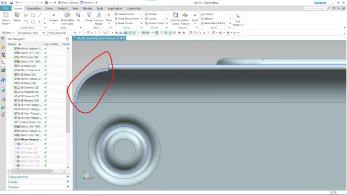
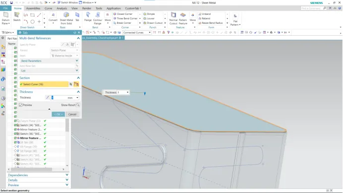
- Flange - A flange of 3 mm web length is added on both sides of the lid which allows it to close the box with paper alignment.
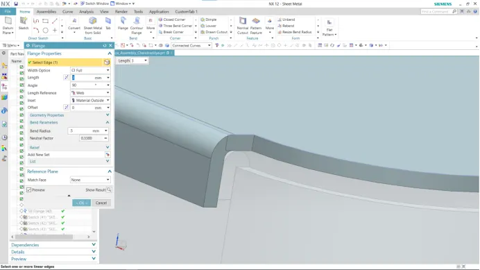
- Tab for hinge - A datum plane is created on the face of the flange perpendicular to the YZ plane and a rectangle is sketched to create a base tab.

- Break Corner - This feature breaks the sharp edges in the corners and makes it round or adds chamfer. It is like the fillet feature in some other CAD software.
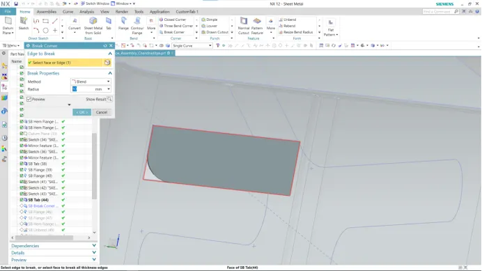
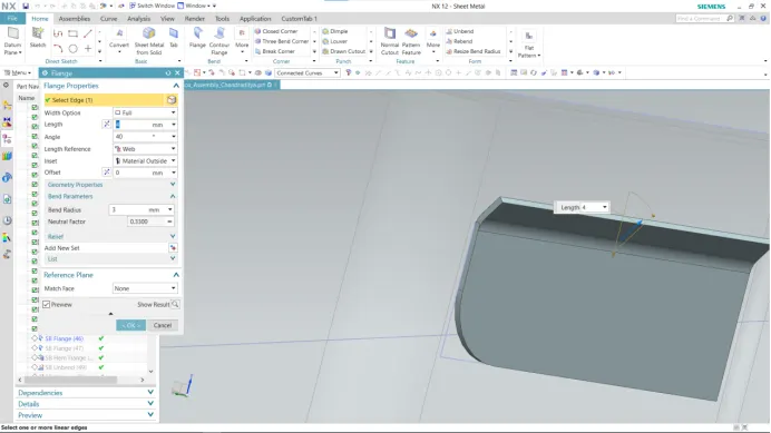
- Flanges - Now, two flanges of 40 degrees bend each of length 4 mm is created adjacent to each other.
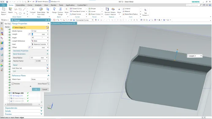
- Hem Flange - An open hem flange of radius 5 mm and angle of 325 degrees is added at the end of the flange to create the hinge for the box lid.
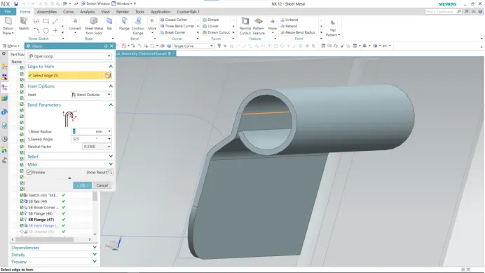
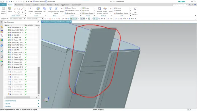
- Unbend - This is a very powerful and very useful tool in NXCAD. It allows all the bends made by various feature to the unbend state at once.
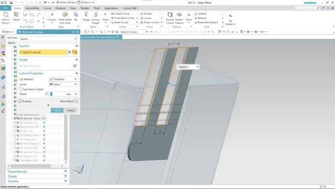
- Normal Cutout - The unbend feature is used and the sketch is created on the face of the hem flange in the flat state. Two rectangles are created as per the requirement for the hinge barrels on both sides. Then the normal cut operation is carried out .
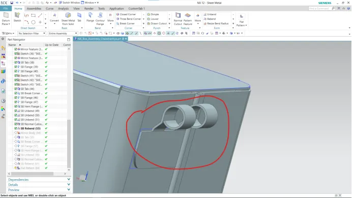
- Rebend - All the features added after the unbend feature are added in the unbend state itself. After the addition of sketches and additional features are completed, the sheetmetal component has to be rebent to the required position. This is done using the rebend feature and selecting all the bends in order or by box selection.
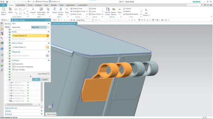
- Mirror Body - Again, the body of this hinge is mirrored to the YZ plane to form the same half on the other side.
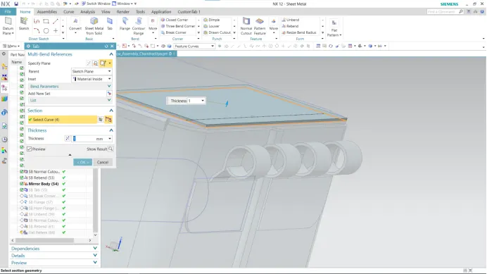
- Tab creation for upper hinge - A datum plane is created on the top face of the lid and the sketch for the tab is created. Now, a base tab is added. This tab will be the base for the upper part of the same hinge. Here, the tab is a single part extended over the length.
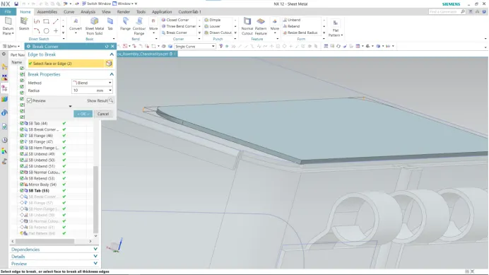
- Break Corner - The break Corner operation is performed in the above-created tab.
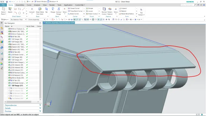
- Flanges - Similar to the earlier part of the hinge, two adjacent flanges are created at an angle of 37 degrees so that the hem flange following this step can be concentric to the earlier one.
- Hem Flange - Similar to the earlier process, an open hem flange of radius 5 mm extended over a 325-degree angle is created.
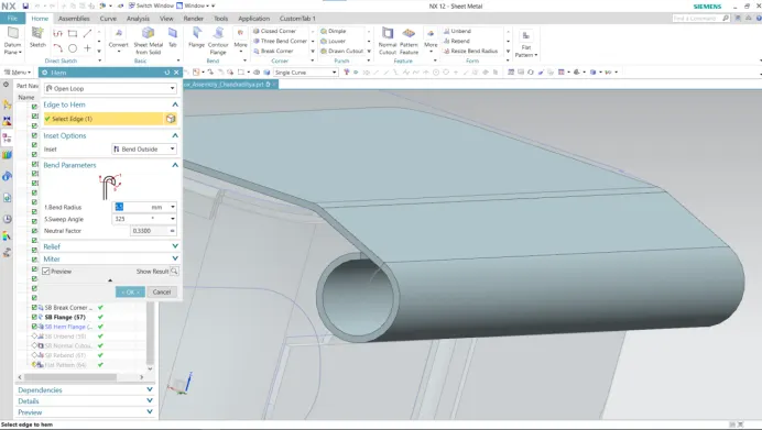
- Normal Cutout - Again, the unbend feature is used and the sketch is created on the face of the hem flange in the flat stage. Four rectangles are created as per the requirement for the hinge barrels on both sides. Then normal cutout operation is created.
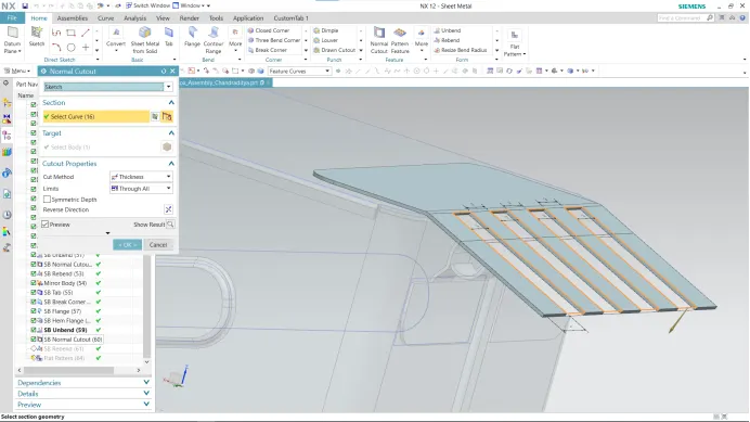
- Rebend - Following the normal cutout feature, rebend is used to get the expected output as shown in the image below.
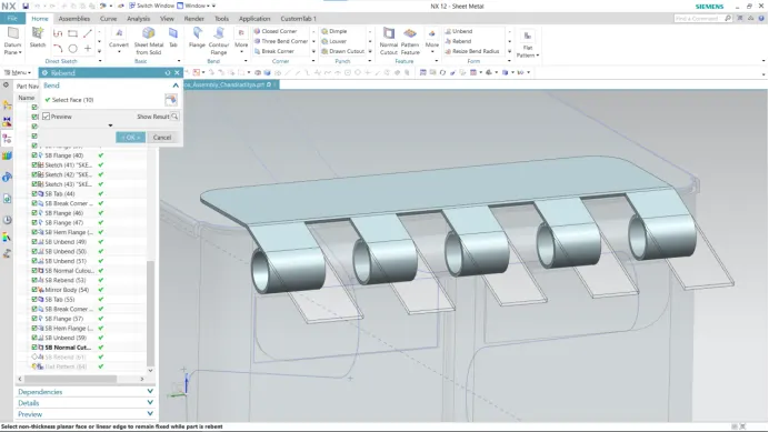
- Design of box assembly - The completion of the box assembly design with the feature in NX CAD is shown here.
- Isometric View -
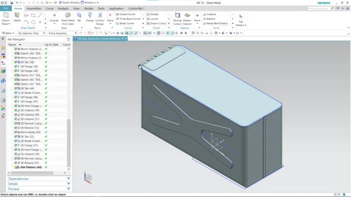
- Top View -
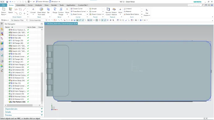
- Right View -
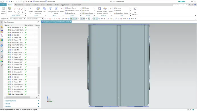
- Bottom View -
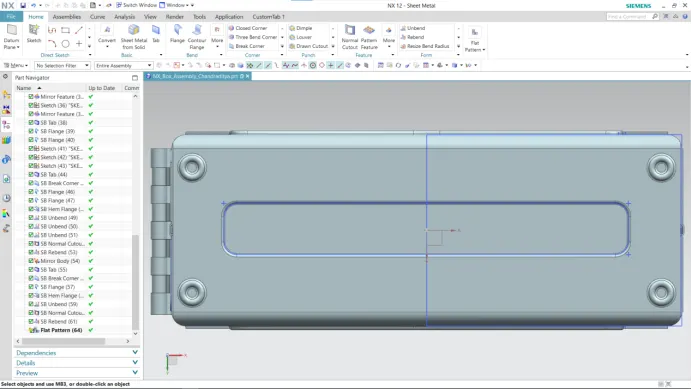
- Left View -
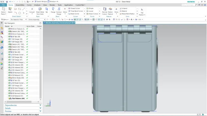
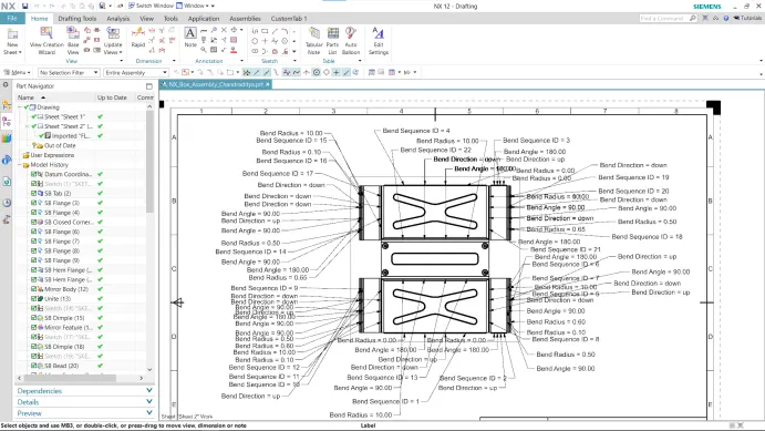
- Drafting -
- Conclusion - In this project, a sheet metal box assembly is successfully designed using Siemens NXCAD sheetmetal application.