Advanced Sheet Metal Design Using NX Cad Challenge_5_Odd Shaped Enclosure
Designing odd shaped enclosure using NXCAD sheet metal application
- Aim - Modelling an odd-shaped enclosure in NXCAD sheetmetal
- Objective - The objective of the project is to design a sheetmetal odd-shaped enclosure using a sheetmetal application in NXCAD and a drafting model using a drawing application in NX.
- Introduction -Sheet Metal is metal formed by an industrial process into thin, flat pieces OR Sheetmetal is a comprehensive cold working process for metal sheets usually below 6mm, including shearing, punching/cutting/folding, riveting, splicing, etc.
- Sheetmetal is one of the fundamental forms used in metalworking and it can be cut and bent into a variety of shapes. Countless everyday objects are fabricated from sheetmetal. Thickness can vary significantly; extremely thin sheets are considered foil or leaf, and pieces thicker than 6mm are considered plate steel or structured steel.
- Sheetmetal is available in flat pieces or coiled strips. The coils are formed by running a continuous sheet of metal through a roll slitter.
- Design Methodology -
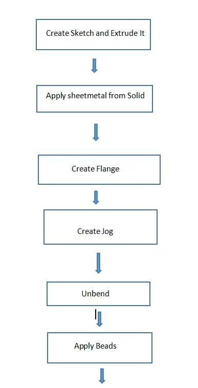
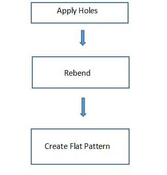
- Description -
- Features used -
The features used in NX CAD in designing sheetmetal casing are -
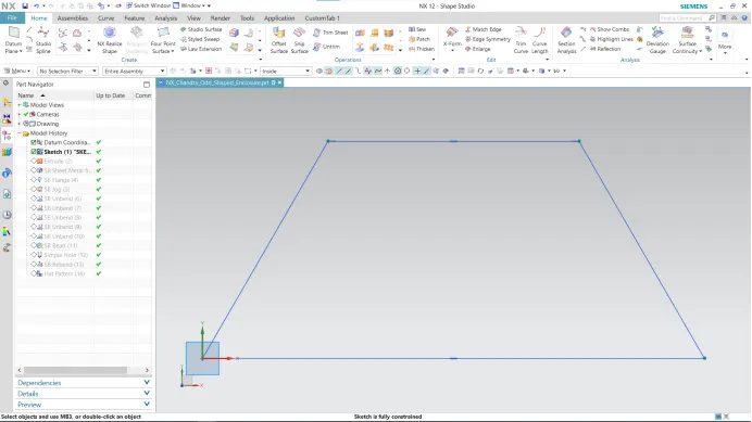
- Creating 2D sketch - 2D Sketch is created on XY, XZ, or YZ plane. With the help of a 2D sketch, we create 3D features.
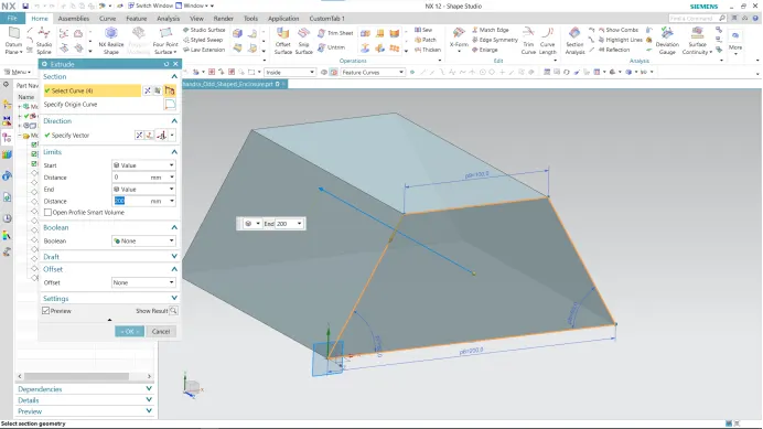
- Extrude - An extrude feature will allow you to take a 2D sketch and add thickness to it in the third dimension.
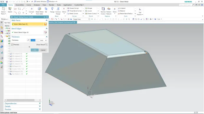
- Sheetmetal from solid body - NX provides a command as sheetmetal from solid which convert a solid body to sheet form. To convert, first, we specify web faces and then specify bend edges. Pre-set values or global values of bend radius and k factor are applied with a specified thickness.
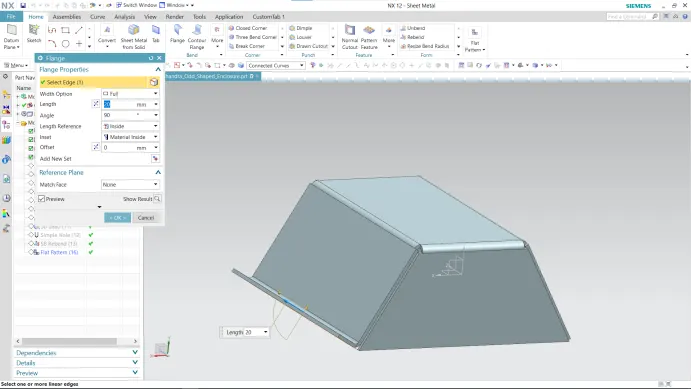
- Flange Feature - The Flange feature adds a flat flange at an angle to the planar face and adds a bend between the two. While creating a flange we have to set different parameters such as the length of the flange, its angle, length reference (inside, outside, or web), and inset (Material inside, Material outside, or bent outside). Other parameters like bend radius, bend relief, and Neutral factor are also needed to be considered.
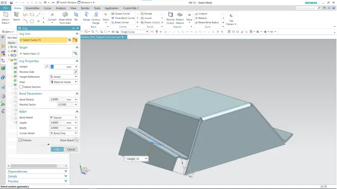
- Jog - A jog is a tool that lifts material on one side of the jog line and adds a flange between two sides. The section for jog must consist of a single line across a planar face. Jog provides rigidity to a part by creating step in tab or face. In the model, we apply jog on the opposite face to the flange.
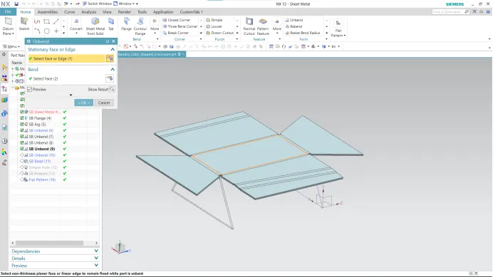
- Unbend - This command is used to unbend the sheetmetal. The punching operation can be performed only by unbending the sheetmetal.
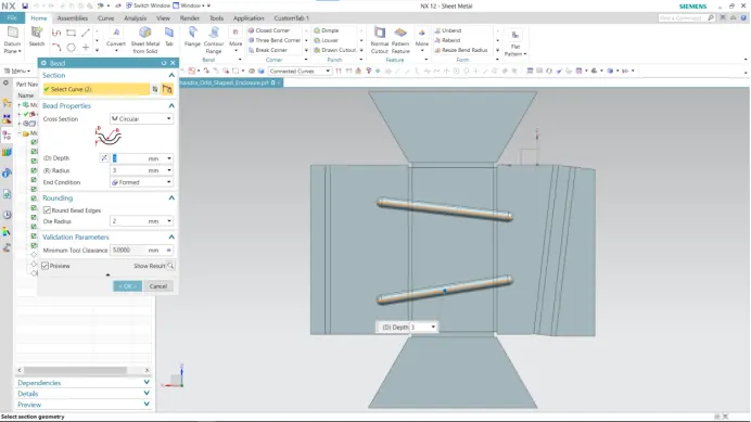
- Bead - The bead is like a raised rib in the sheetmetal panel. It requires that you have at least one sheet metal panel in the active part as well as an open or closed-loop sketch.
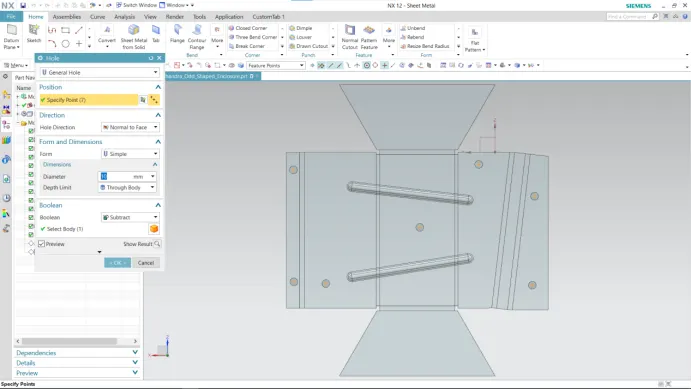
- Holes - Holes are added to provide alignment to the enclosure. In NX the hole feature has options like general type, counterbore, countersink, etc. Position, Diameter, and depth are important inputs to applying a hole to a body.
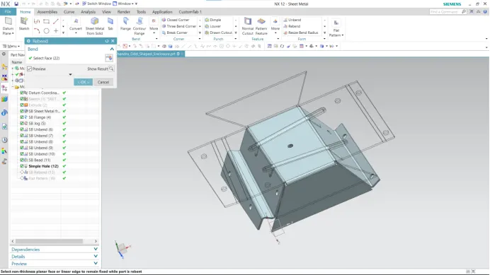
- Rebend - Rebend feature is used to get the original bend shape after performing operations like dimple, bead, etc.
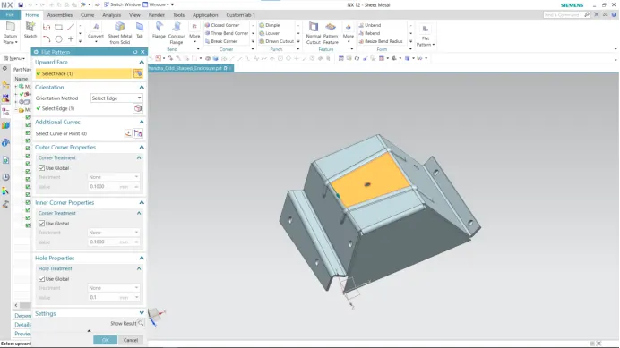
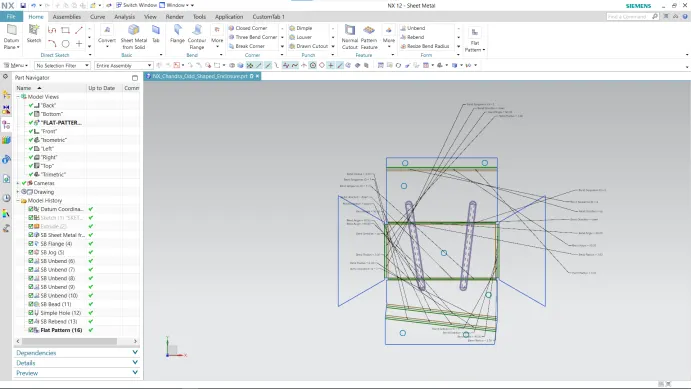
- Flat Pattern - This feature is used to create an automatically flattened version of sheet metal parts and prepare the model for the manufacturing process. This flat pattern remains the last feature in the model tree. A flat pattern ensures the manufacturability of components.
- Drafting -
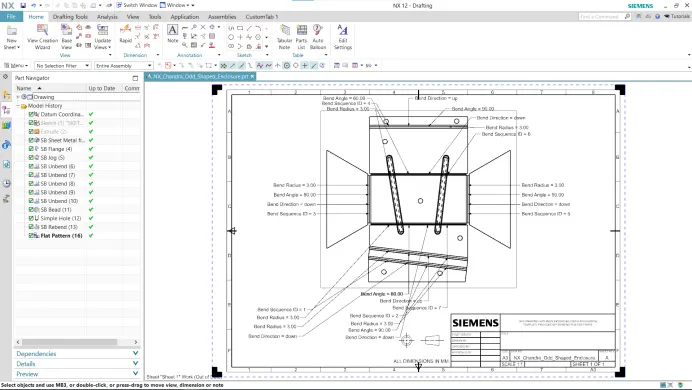
It refers to creating technical drawings that communicate dimensions, view of component geometry, and other features that are performed over part in 2D or 3D. The draft of the drawing is prepared which include annotation, dimension, relation, etc, which helps people from the manufacturing or production department with the component.
- Model Views -
- Front View -
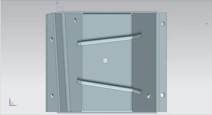
- Top View -
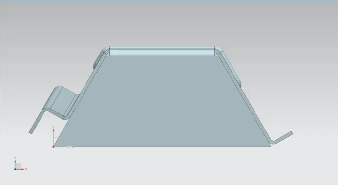
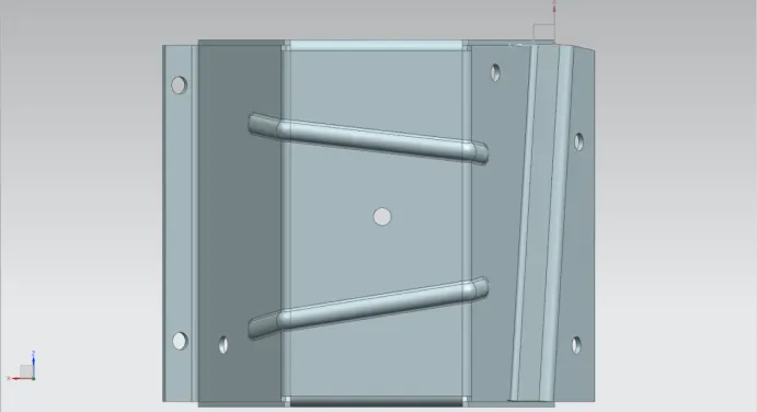
- Back View -
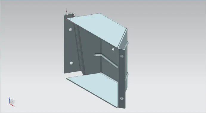
- Isometric View -
- Conclusion -
The design of the odd-shaped enclosure is completed in NXCAD sheet metal application.