Wiring harness design in CATIA V5 - 3D modeling Week 5 & 6 Challenge
Task: Wiring harness design in CATIA V5 - 3D modeling Week 5 & 6 Challenge
Objective:
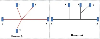
To Route the following Two harness layout in Electrical workbench. Make assumption for harness bundle diameters. Use the connectors provided. After completion of routing,
- To Check the bundle Continuity,
- To Add annotation to all connectors.
- To Check for the bundle warning. Add snap.
- To Generate CAT.part of harness assembly and convert is in. igs format.
Harness Layout:
Procedure:
The electrical connectors are represented by numbers in the above figure. There are 8 different types of connectors at 10 different locations.
1. All Connectors Are Electrically Defined and Connect Accordingly.
2. Bundle continuity has to be checked for the two created harness.
3. After the two Harnesses are created, the next objective is to have them interconnected electrically.
4. Check for bundle warnings in Harness A and Harness B.
5. Add annotations to all the connectors in Harness A and Harness B.
6. The final objective of this project is to convert the final harness file into IGS file format.
Construction of the Model:
Step 1: All Connectors Are Electrically Defined and Connect Accordingly.
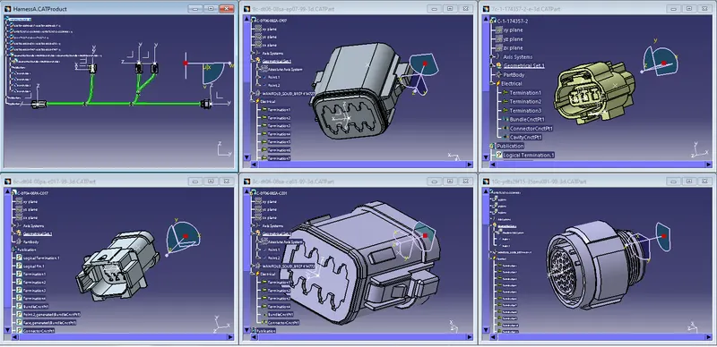
Initially We Have to defined All the Connectoes Electrically and Connect all Connectors As Mentioned in the Harness A Layout.
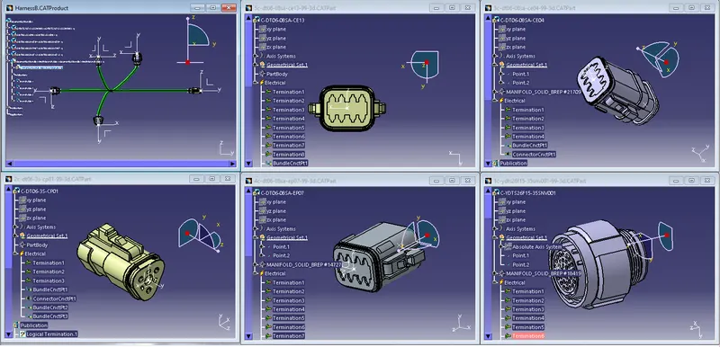
then, We Have to defined All the Connectoes Electrically and Connect all Connectors As Mentioned in the Harness B Layout.
Step 2: Bundle continuity has to be checked for the two created harness.
Harness A:
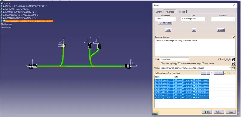
We Have to Check Bundle continuity has to be checked for the Harness A and Ensure it is Fully Connected.
Harness B:
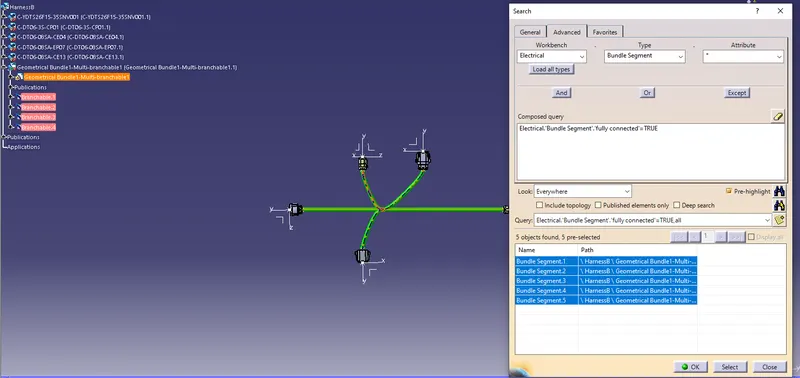
We Have to Check Bundle continuity has to be checked for the Harness B and Ensure it is Fully Connected.
Step 3: Interconnection:
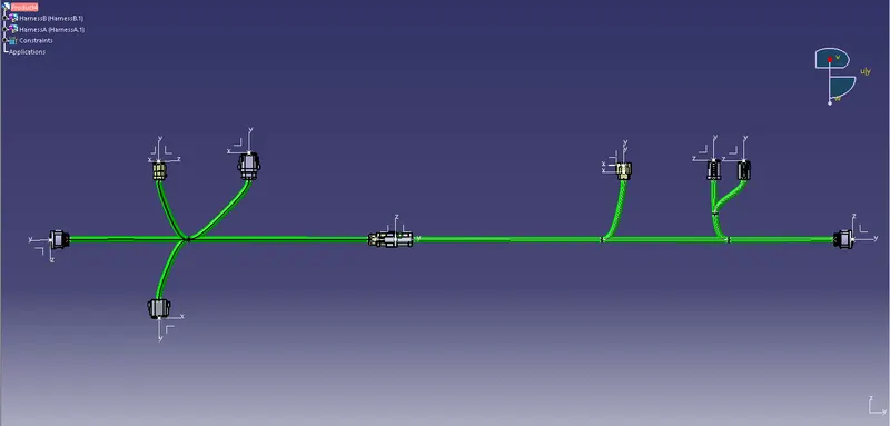
Connecting Two Harness Layout , Use manipulation tools found in the assembly design workbench in CATIA V5 to connect the two wiring harness. But, one should remember that by following this process the two harnesses will not be connected electrically. To properly connect them we have to go to Electrical Assembly Design workbench and use "connect electrical devices" feature.
Step 4: Check for bundle warnings in Harness A and Harness B:
Harness A Warning:
Geometric Bundle Warning is Displayed While Connecting the Connector 7 With Harness, To avoid This Warning Issue the Branch Point Has Been Replace Their Position For the Correct Position.
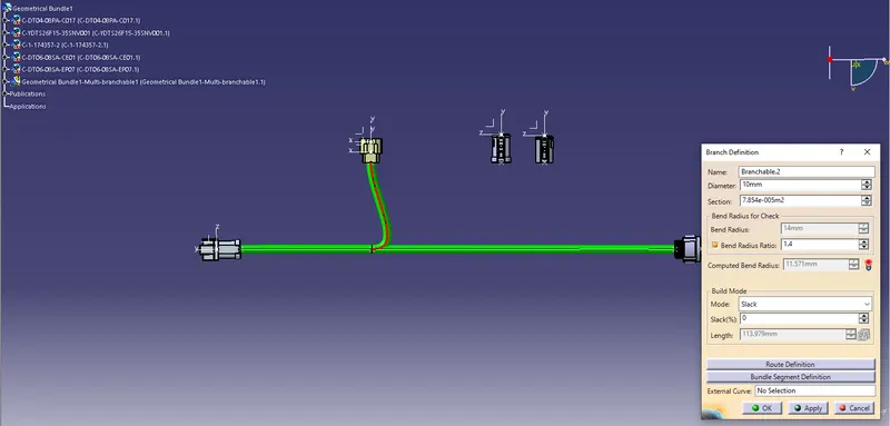
Here,the Branch Point Has Been Moved to Connect Properly.
Harness B Warning:
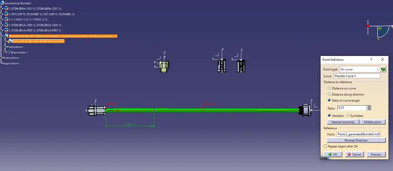
Geometric Bundle Warning is Displayed While Connecting the Connector 2 With Harness, To avoid This Warning Issue the Direction of the routing Definition Has Been Reversed and Branch Point Also Moved For the Correct Position.
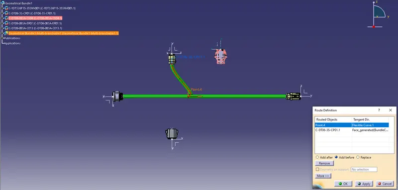
Here,the Branch Point Has Been Moved to Connect Properly, also Reverse the Direction Of Bundle Segment.
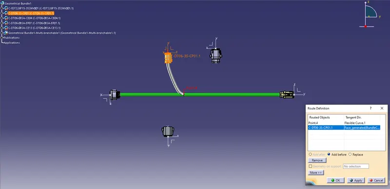
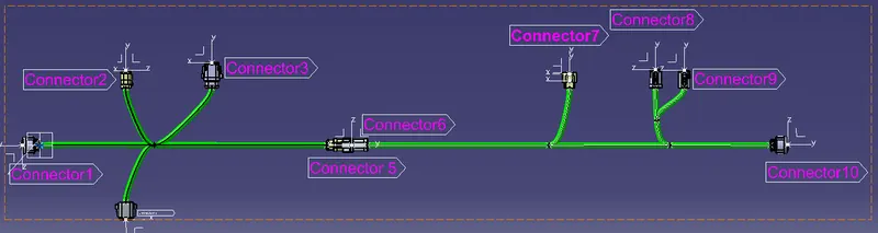
Step 5 : Annotations:
After annotations are added to all the connectors we should change the annotation font size and color so they are easily visible.
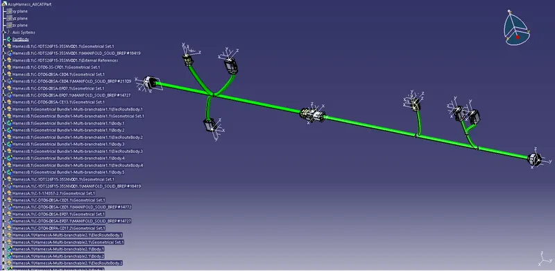
Step 6: Converting CatPart File to IGS Format:
Once the CAT part is created the whole product file is converted into a single part. At this stage, it can be noticed that all the bundle segments are grey in color. So, we will go back and add green color to each bundle segment so that they look same as the Final Harness Assembly.
Conclusion:
Thus, the Routing two electrical harnesses as per the given layout and interconnect them as a single harness assembly and then check for bundle continuity, bundle warnings, and then give annotations to the final harness assembly has Been Checked and Created.