Wiring harness design in CATIA V5 - 3D modeling Week 5 & 6 Challenge
Wiring harness design in CATIA V5 - 3D modeling
Q1. Route the following harness layout in Electrical workbench. Make assumption for harness bundle diameters. Use the connectors provided. After completion of routing,
- Check the bundle Continuity. Add snap of result in submission
- Add annotation to all connectors. Make an assumptions for annotations like connect 1 , 2 etc
- Check for the bundle warning. Add snap.
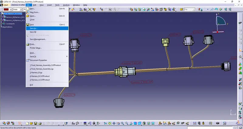
- Generate CAT.part of harness assembly and convert is in. igs format.
Click here for CAD data and routing mapping data
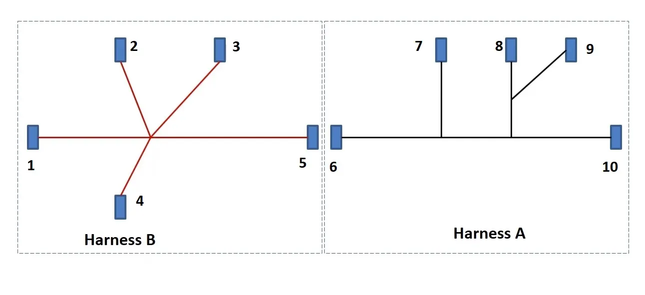
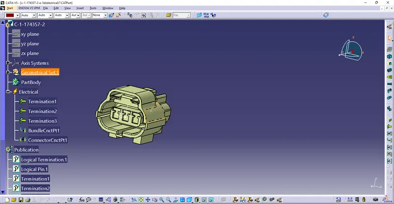
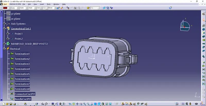
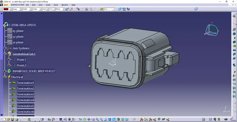
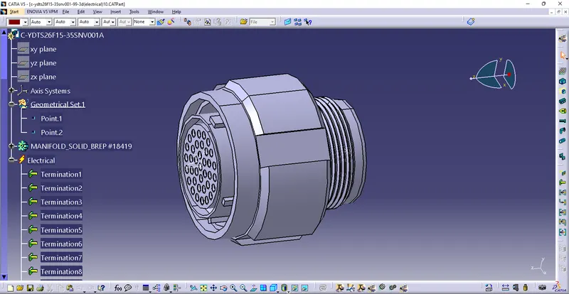
First we need to convert all the connectors into Electrical parts by following method-
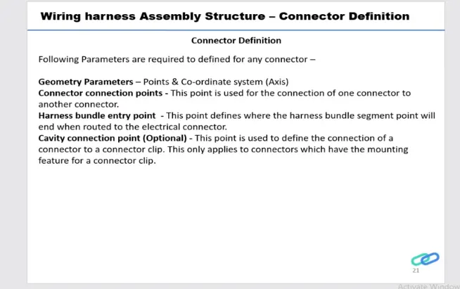
Geometry Parameters-
Create a Point & Axis system-
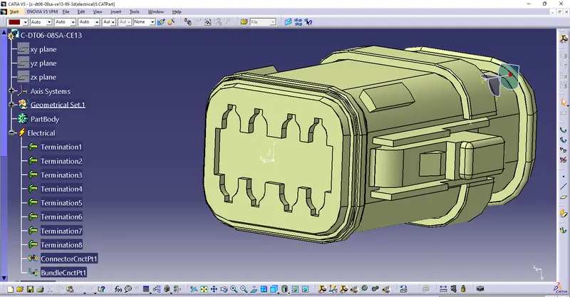
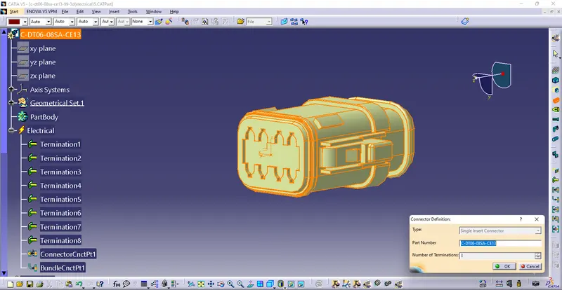
Deifine part as Connector-
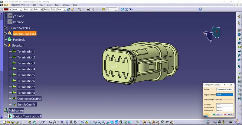
Define Connector Connection Point-
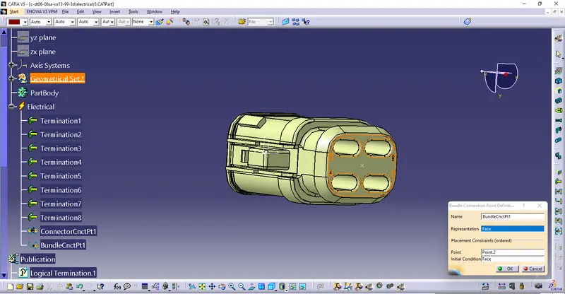
Define Bundle Connection Point-
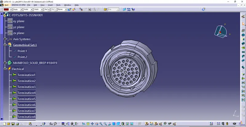
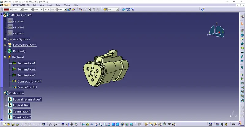
Now we have to define all remaining parts into Electrical parts-
(1)
(2)
(3)
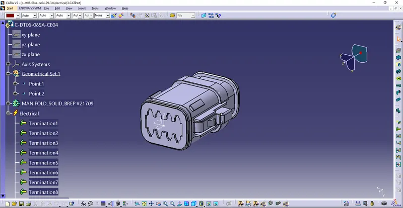
(4)
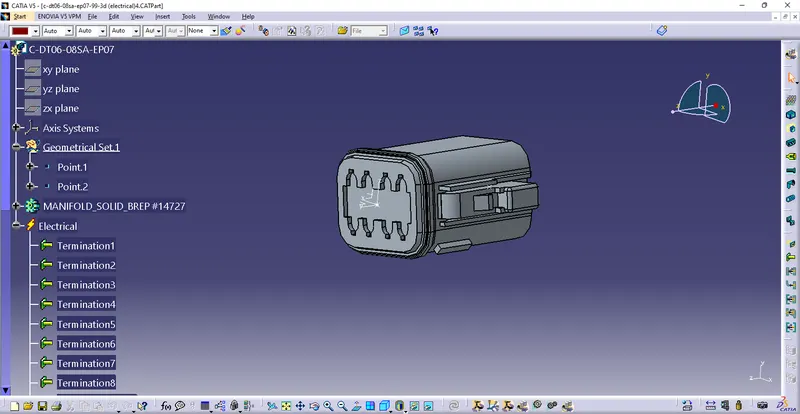
(5)
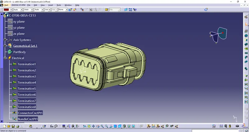
(6)
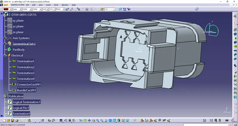
(7)
(8)
(9)
(10)
Create harness A and harness B as shown below
First, all the connectors are placed at their desired locations. Second, bundle segments are created between the connectors with branch points and branches as shown below.
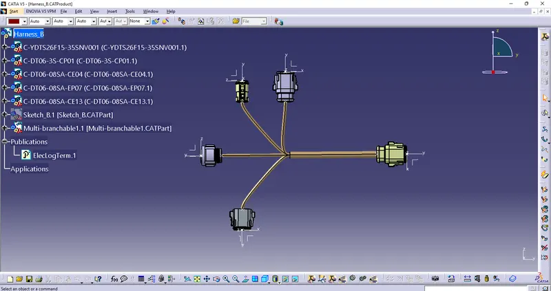
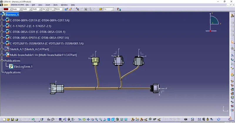
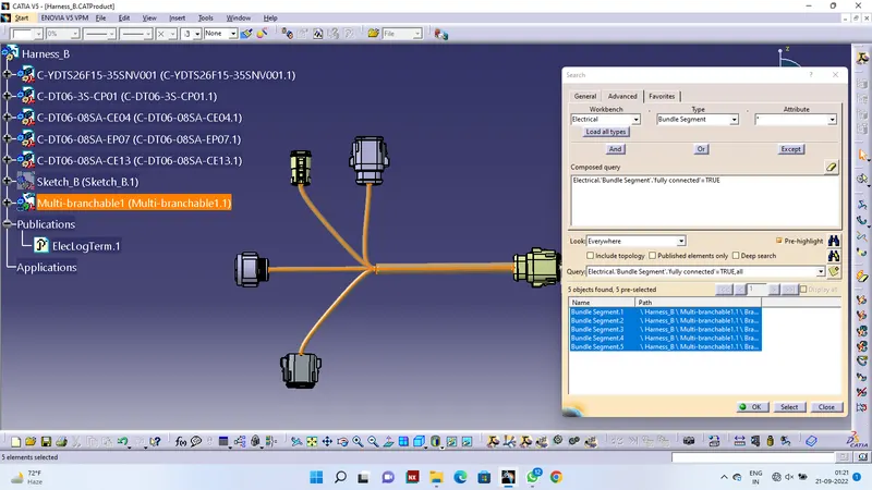
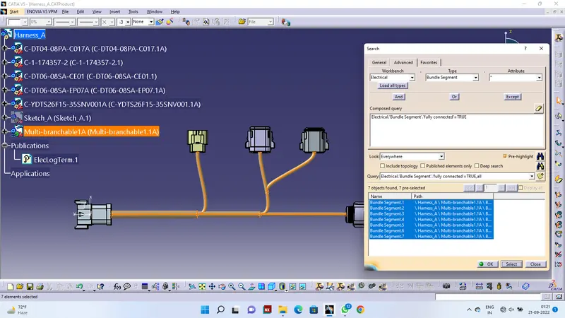
Now we have to check the bundle continuity.
For Harness B-
For Harness A-
Interconnect Harness A & B Using Electrical Assembly-
- Create a New Product name as Final Harness Assembly.
- Add Existing Components like Harness A & Harness B
- Open Electrical Assembly Workbench
- Use Connect Electrical Device to connect two Harness Bundle Sagment.
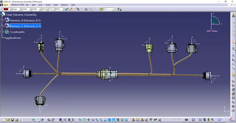
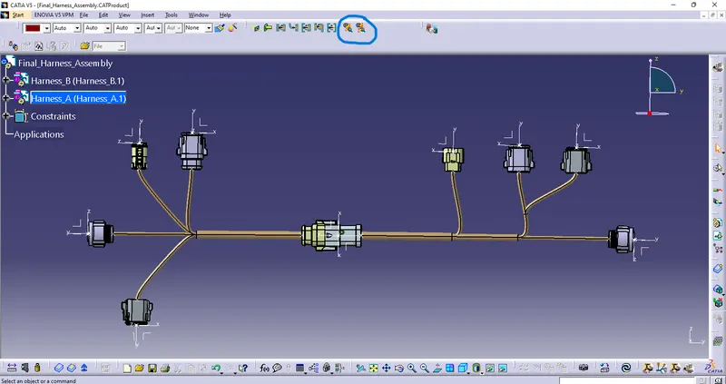
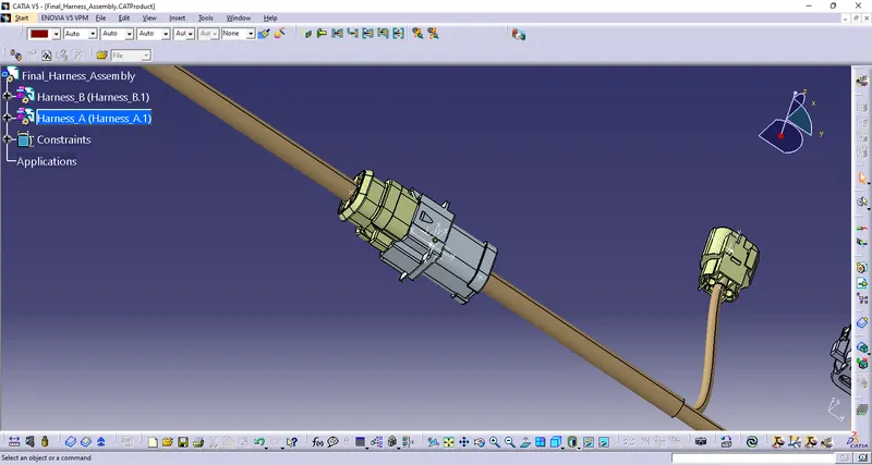
we will check bundle warnings in Harness A and B.
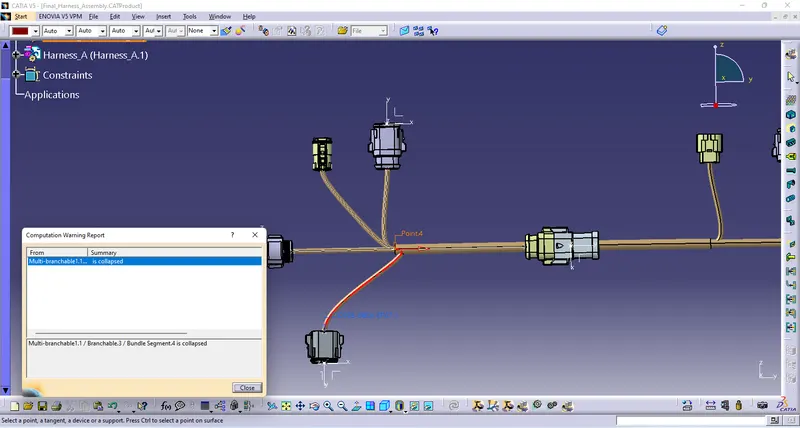
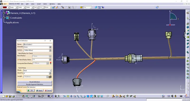
We have alert(warning) in computed Bend radius (computed bend radius is less then bend radius)
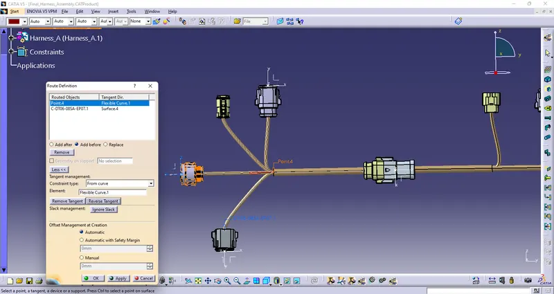
to solve the issue we changed tangency at point 4 and warning realeased.
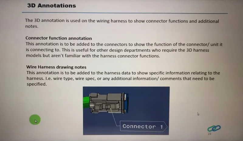
Now we will add annotation to all connectors
Annotations are used to show connector functions and additional information. They are defined in Assembly Design Workbench of CATIA V5.
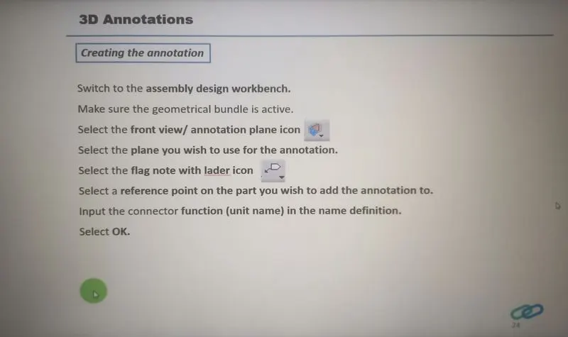
Steps-
- first select plane to use annotation
- select flag note with lader icon
- select a point or part we have to add annotation
- input name of part or other function
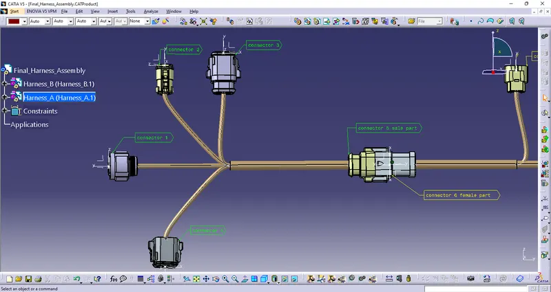
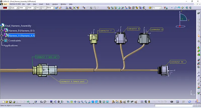
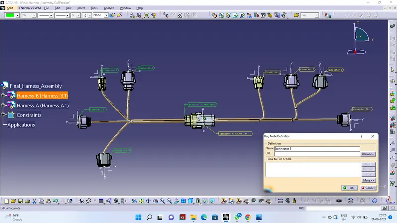
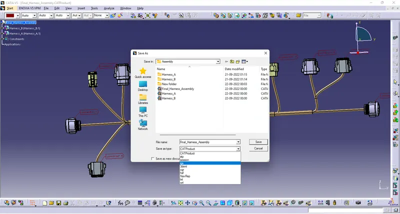
At last we will covert our product file into IGS formate for covert file into igs we will use following steps-
- Go to file
- click on save as
- choose as igs formate
- click on save
CONCLUSION- Routing of the two electrical harnesses as per the given layout was achieved and interconnection between them as a single harness assembly was established. Both the harness were checked and corrected for bundle warnings and bundle continuity. At the very end, annotations were added to all the connectors and the final harness assembly file was converted into IGS format.