Wiring harness design in CATIA V5 - 3D modeling Week 5 & 6 Challenge
AIM- Route two electrical harnesses as per the given layout and interconnect them as a single harness assembly and then check for bundle continuity, bundle warnings.
OBJECTIVE-
- The objective of this project is to first route the two Harness A and Harness B as per the given harness layout.
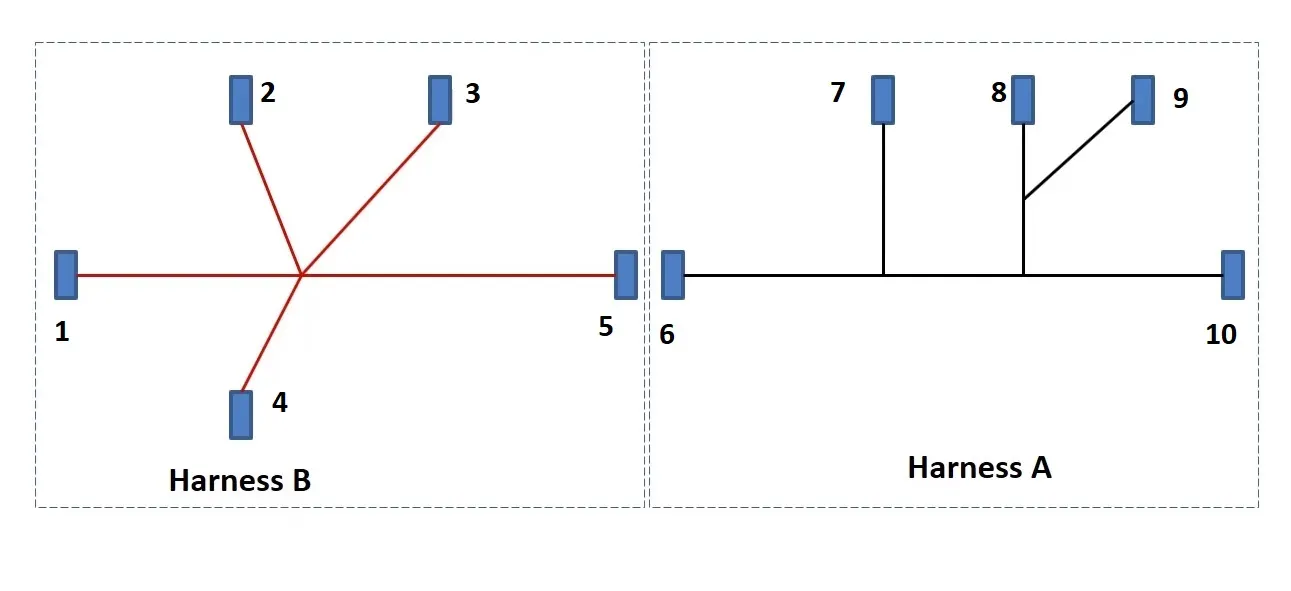
Figure 1: Shows the layout of two Harness A and Harness B
1.The electrical connectors are represented by numbers in the above figure. There are 8 different types of connectors at 10 different locations.
2. Bundle continuity has to be checked for the two created harness.
3. After the two Harnesses are created, the next objective is to have them interconnected electrically.
4. Check for bundle warnings in Harness A and Harness B.
CONTENT-
The following steps are to be done to complete this project.
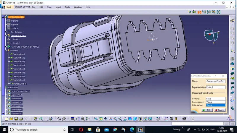
STEP1-Define all the electrical connectors geometrically and electrically so that they can be used in the wiring harness.
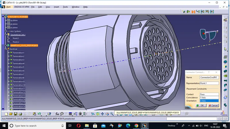
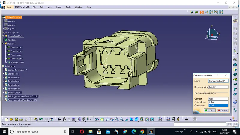
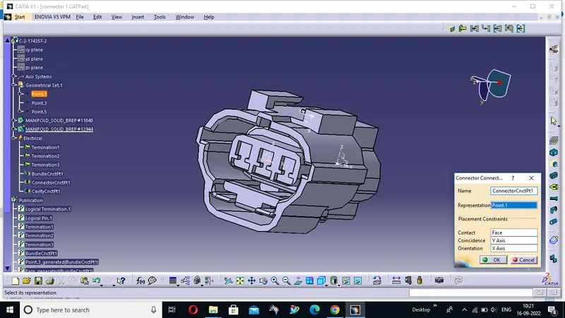
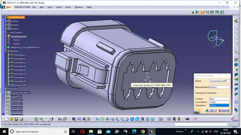
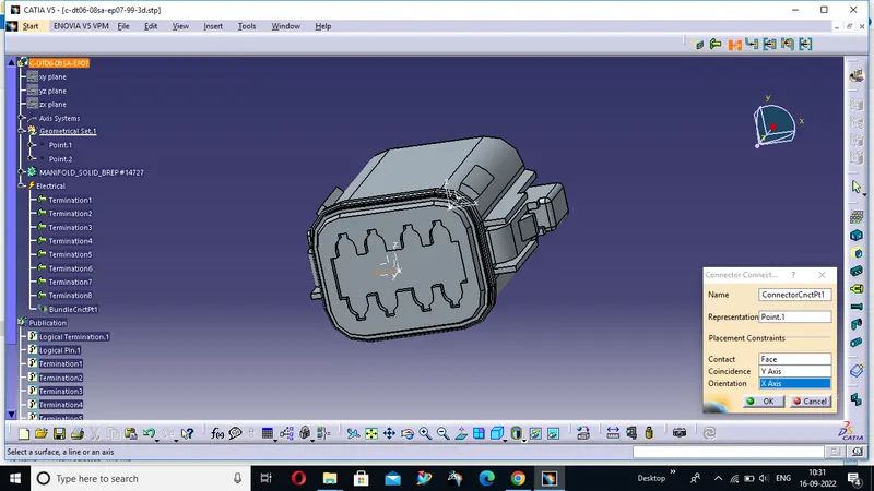
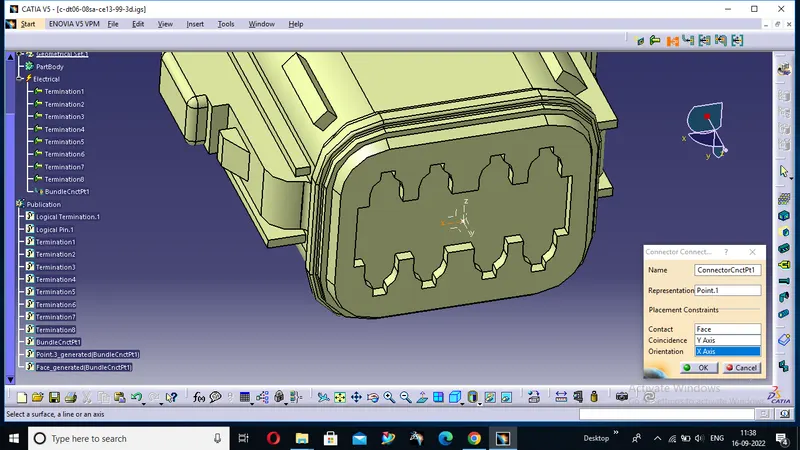
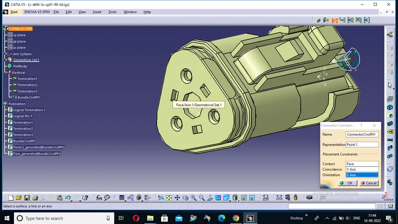
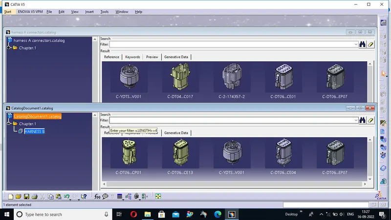
the catalouge of all the connectors are given below
STEP2-Create harness A and harness B as shown below by using the electrical harness workbench in CATIA V5.
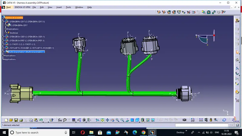
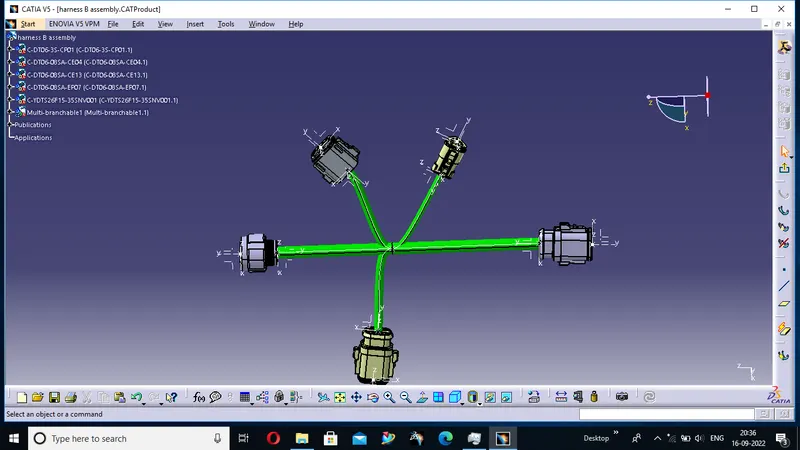
First, all the connectors are placed at their desired locations. Second, bundle segments are created between the connectors with branch points and branches as shown below.
Bundle diameter is assumed to be 10mm, 7mm and 5mm for different bundle segments. slack is given as 0% for all the bundle segments.
HARNESS A :--
HARNESS B:--
STEP 3:--
In this step, we have to interconnect the Wiring Harness A and Harness B electrically. There are a few steps that have to be followed to connect the two harnesses electrically.
First, make a new product file in CATIA and rename it as "HARNESS A + B ASSEMBLY".
Second, copy both harness A and harness B and paste it into the newly created product file to make the final harness assembly as shown below.
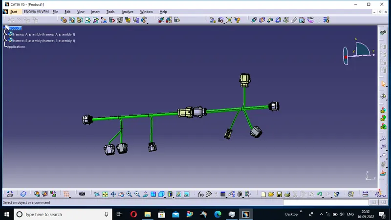
Third, at this stage, we can use manipulation tools found in the assembly design workbench in CATIA V5 to connect the two wiring harness. But, one should remember that by following this process the two harnesses will not be connected electrically. To properly connect them we have to go to Electrical Assembly Design workbench and use "connect electrical devices" feature as shown below.
Fourth, once we are inside the electrical assembly design workbench we should electrically connect the male and female connectors as shown below.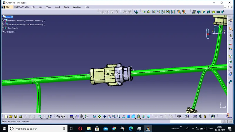
THIS IS OUR ASSEMBLY A+ B
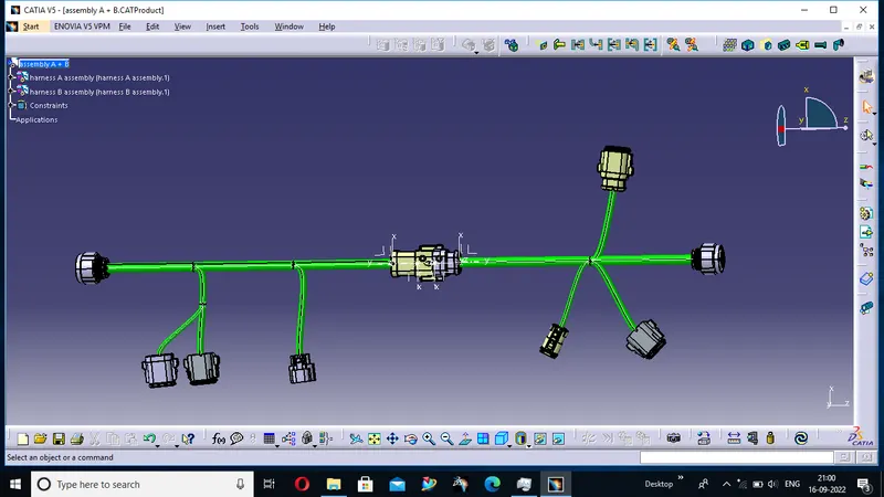
CONCLUSION- Routing of the two electrical harnesses as per the given layout was achieved and interconnection between them as a single harness assembly was established. Both the harness were checked and corrected for bundle warnings and bundle continuity.
THE CATPART IS GIVEN IN A SINGLE FOLDER.