Wiring harness design in CATIA V5 - 3D modeling Week 5 & 6 Challenge
Objectives:
- To route the given harness layout in Electrical workbench
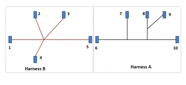
2.To check the bundle continuity
3. To check bundle warning
4. To add annotation to all connectors
5. To generate CAT part of harness assembly and convert it in iges format
Wire harness routing as per given harness layout in electrical workbench
Routing process is carried out in following steps
- Creation of required product files and geometric bundles
- Download the connector 3D data and define all the connectors as electrical components. Then define all the necessary connection points in the connectors.
- Import all the connector components into the ‘Geometrical bundle assembly’
- Define the ‘Mechanical assembly’ into ‘Electrical assembly’
- Ensure that all the electrical parts inserted are now in ‘Geometrical Bundle’. Now place each electrical part into its correct position.
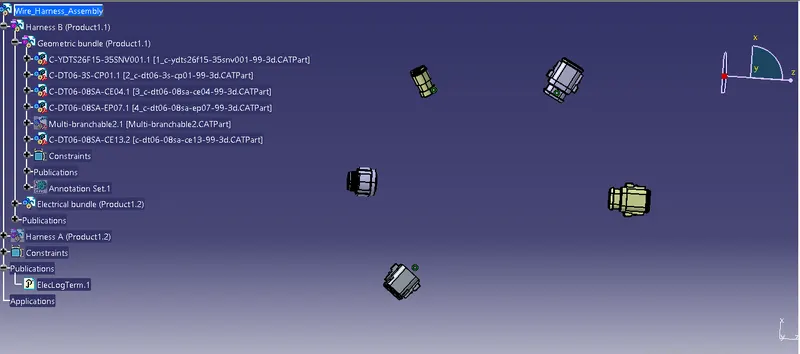
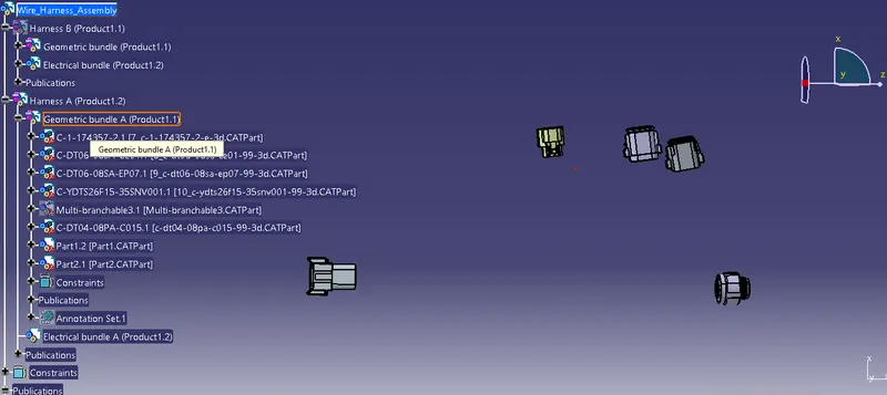
6.Switch to the electrical harness assembly workbench
7.Ensure that your harness geometrical bundle is highlighted
8. Select the ‘Multi-branchable document icon’
9. In the branch definition box input all the required parameters
10. Ensure that the bend radius ratio is set to 1.4 or greater than 1.5
11. Ensure that the build mode is set to ‘Slack’
Final images of Harness A and Harness B layout is shown below
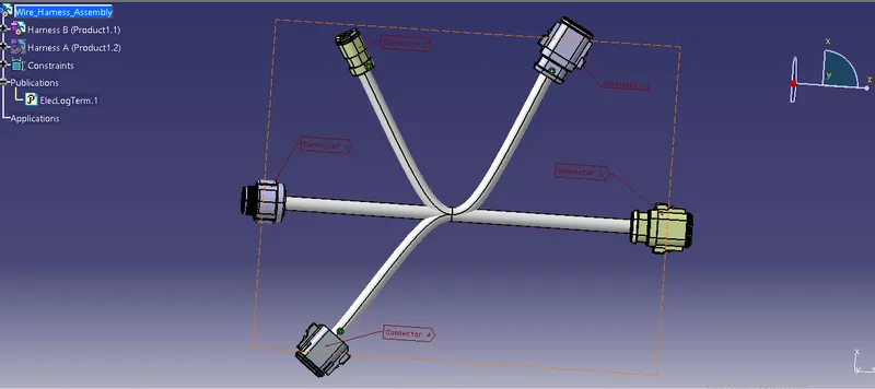
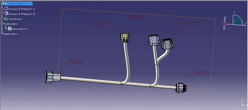
12. Connecting Harness B and Harness A: Switch to the electrical assembly design workbench. Use ‘Connect electrical devices’ command to connect harness A and harness B
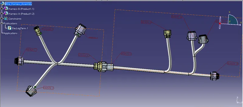
Checking the bundle continuity
This analysis is performed to ensure that there exists no discontinuities in the harness layout. It is carried out in following steps.
- Under ‘Edit’ tab, select ‘Search’ command. It opens a new dialogue box
- In the new dialogue box select ‘Advanced’ settings. Now set the following parameters
- Workbench – Electrical
- Type – Bundle segment
- Attribute – Fully connected
- Select ‘Attribute criterion’ as ‘True’
- Following result is obtained
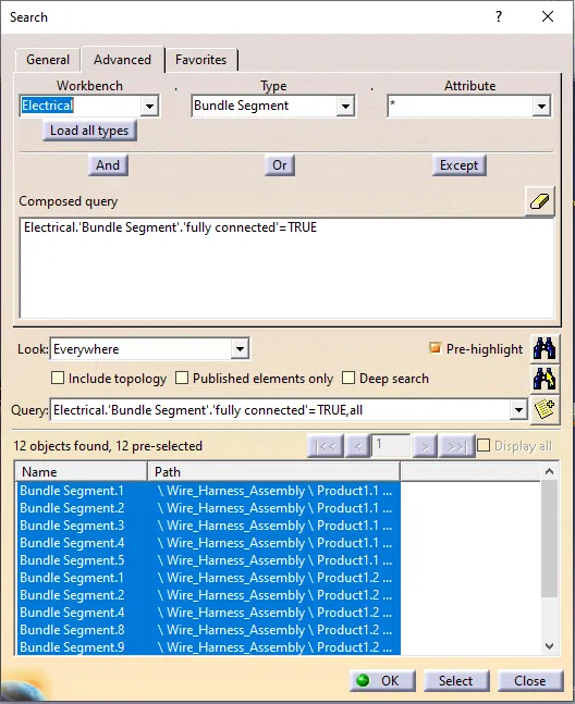
From the above result it is clear that there exists continuity in the wiring harness layout.
To check Bundle warnings
It is possible to get warnings when routing your wire harness. These warnings are usually displayed in the tree structure of the wire harness geometrical bundle. These warnings are usually related to the bend radius, bundle diameter or vector position of bundle segments. If there are any issues with the above then a yellow flash warning symbol will appear in the tree structure of the geometrical bundle. These warnings can be checked out in following way
- Switch to the ‘Electrical harness installation’ workbench
- Select the bundle segment from the tree
- Select the ‘Branch definition’ icon
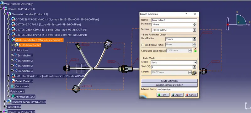
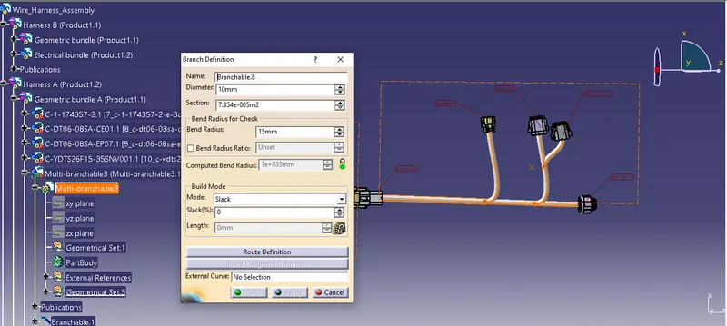
From the above two images it is clear that, there exist no bundle warnings in both Harness A and Harness B
Adding annotations to all connectors
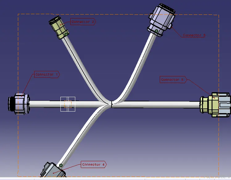
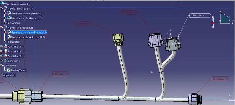
The 3D annotations are used on the wire harness to show the connector name, functions and additional notes. This is useful for other design departments who requires the 3D harness models but aren’t familiar with the harness connector functions.
- Switch to the assembly design workbench
- Make sure the geometrical bundle is active
- Select the front view/annotation plane icon
- Select the flag note with leader icon
- Select a reference point on the part you wish to add the annotation to
- Input the connector name or function in the name definition
Generation of CAT part of harness assembly and converting it into IGES format
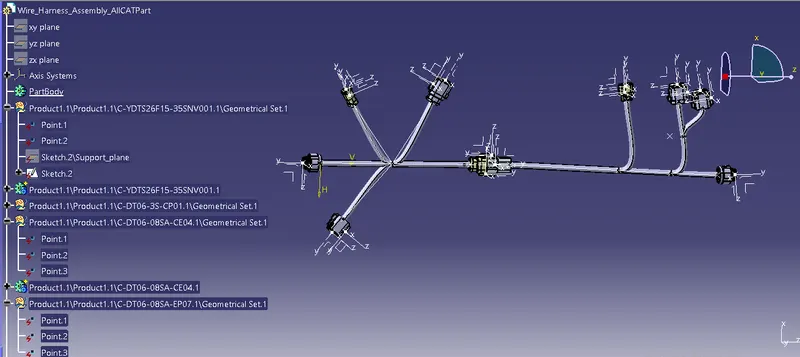
Sometimes it is necessary to create a CAT Part file of the 3D wire harness for review and releasing purposes. This CAT Part can then be converted to IGES or STEP files. This involves following steps
- Switch to ‘Assembly’ workbench. Select ‘Tools’ tab
- Select ‘Generate CAT Part from product’
Conclusion
- Routing is completed as per the given harness layout
- Bundle continuity is checked out and the results are satisfactory
- Bundle warnings are checked out and found that there exists no bundle warnings
- Annotations are added to all connectors
- CAT Part file and IGES file are generated and attached