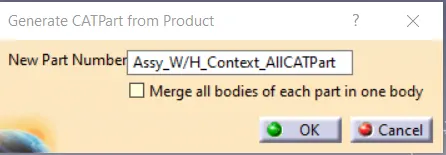
Wiring harness design in CATIA V5 - 3D modeling Week 5 & 6 Challenge
Part 1: - Defining all connectors electrically: - (An example shown here for one of the parts, all parts are defined in the same way)
1. Defining the connector connection point, bundle connection point and the axis system mecahnically in part design: -
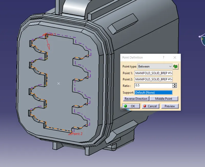
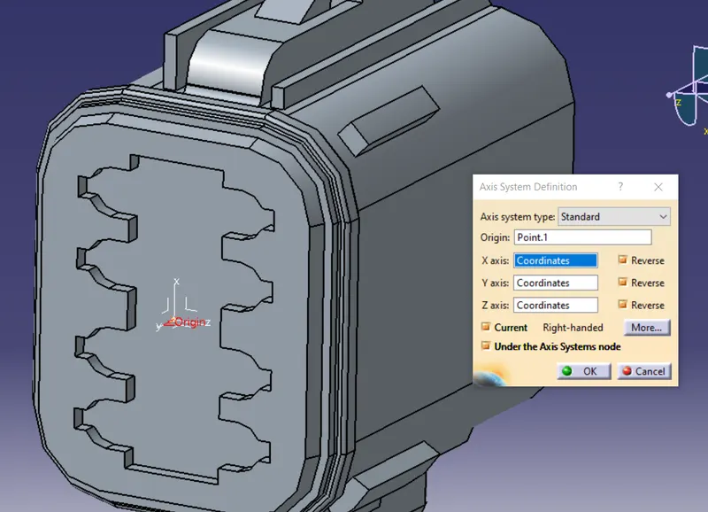
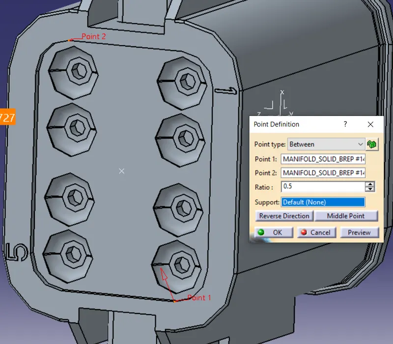
2. Defining the connector, connector connection point and bundle connection point electrically in electrical part design: -
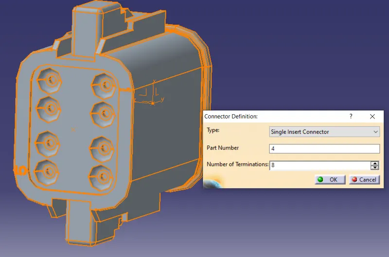
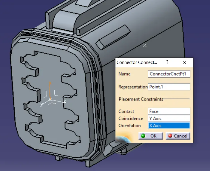
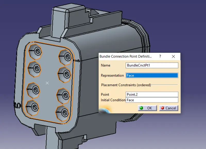
3 Making a new catalogue and adding parts into it.
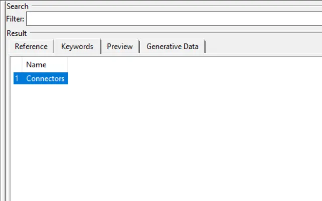
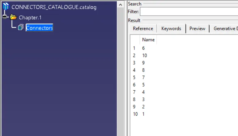
Part 2: - Making Geometrical bundle for Harness A (NOTE - No constraints are taken for the dimensions between the connectors/branches/branching points- they are completely random, as none mentioned in the diagram given for challenge)
1. Arranging the diagram as per diagram
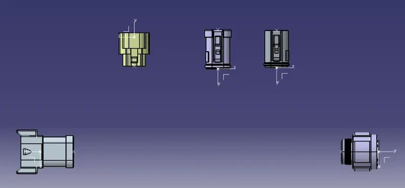
2. Defining the geometrical bundle electrically in electrical harness assembly workbench
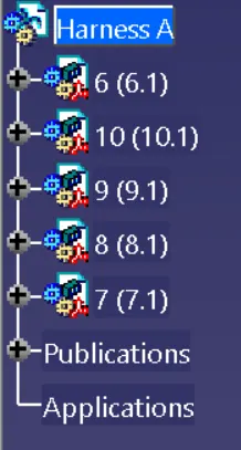
3. Defining the main bundle with diam 10mm
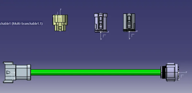
4. Defining the multi branchable point for connector 7 and making the branch with 8mm diameter
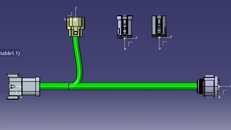
5 . Defining the multi branchable point for connector 8 and making the branch with 8mm diameter
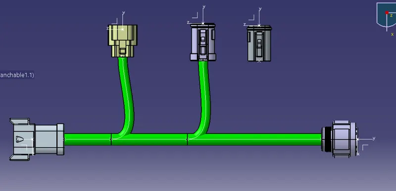
6. Defining the multi branchable point for connector 9 and making the branch with 5mm diameter
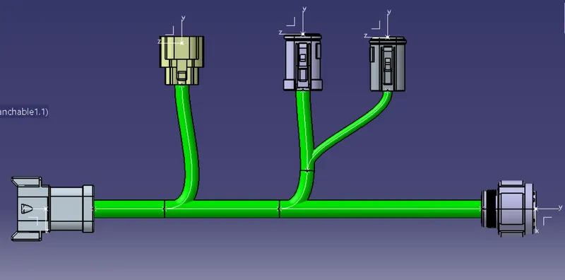
7 Checking bundle continuity: - No issues found
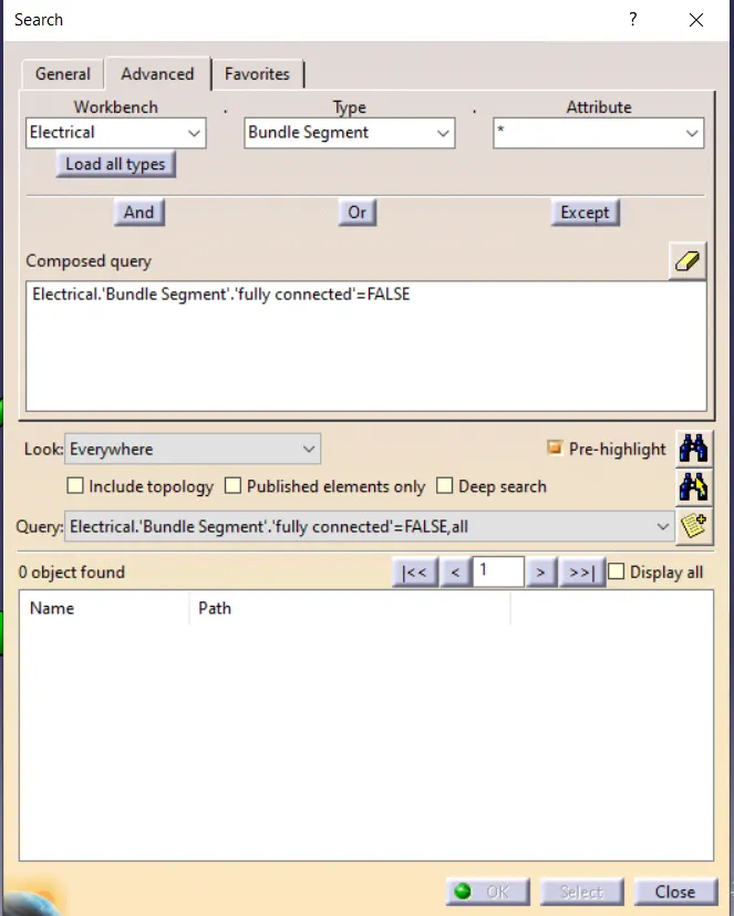
8. Add annotations + No bundle warnings found (snap shown below)
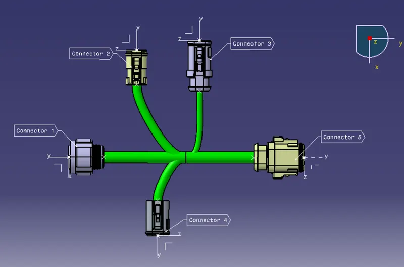
Part 3: - Making Geometrical bundle for Harness B (NOTE - No constraints are taken for the dimensions between the connectors/branches/branching points- they are completely random, as none mentioned in the diagram given for challenge)
1. Arranging the diagram as per diagram
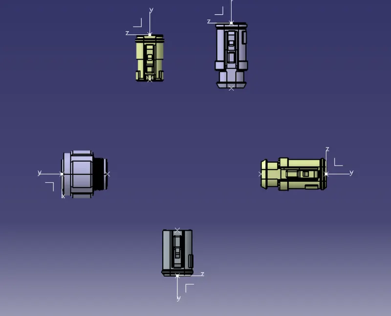
2. Defining the geometrical bundle electrically in electrical harness assembly workbench
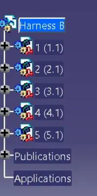
3. Defining the main bundle with diam 10mm
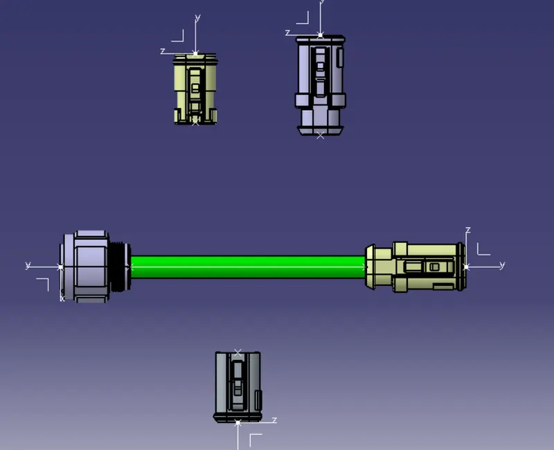
4. Defining the multi branchable point and , for connector 2 making the branch with 8mm diameter
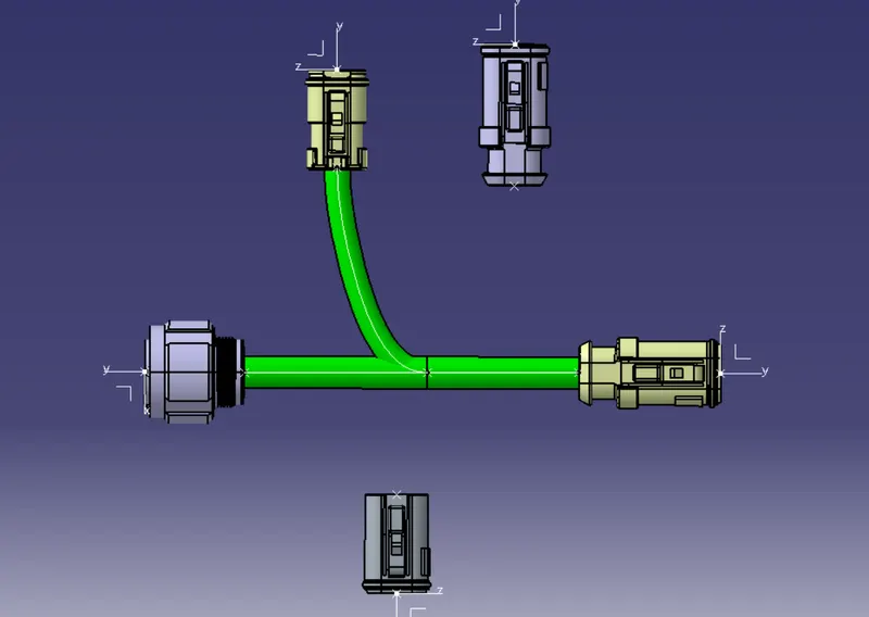
5 . From the multi branchable point, make branch for connector 3 with 5mm diameter
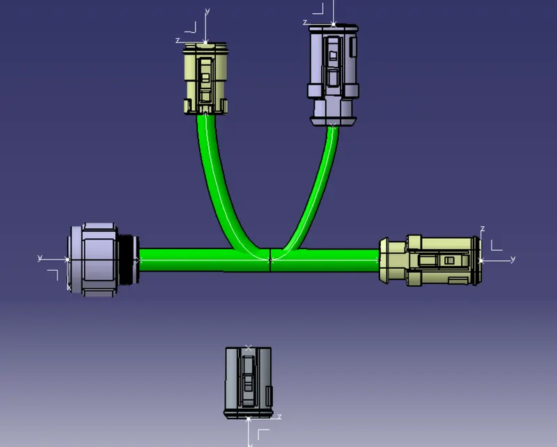
6. From the multi branchable point, make branch for connector 4 with 8mm diameter
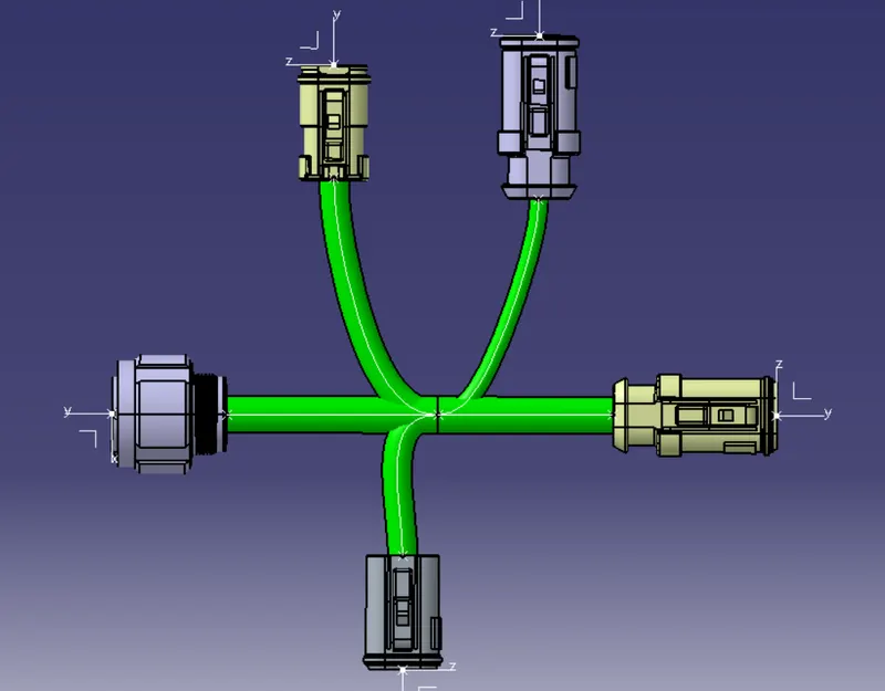
7. Checking bundle continuity: - No issues found
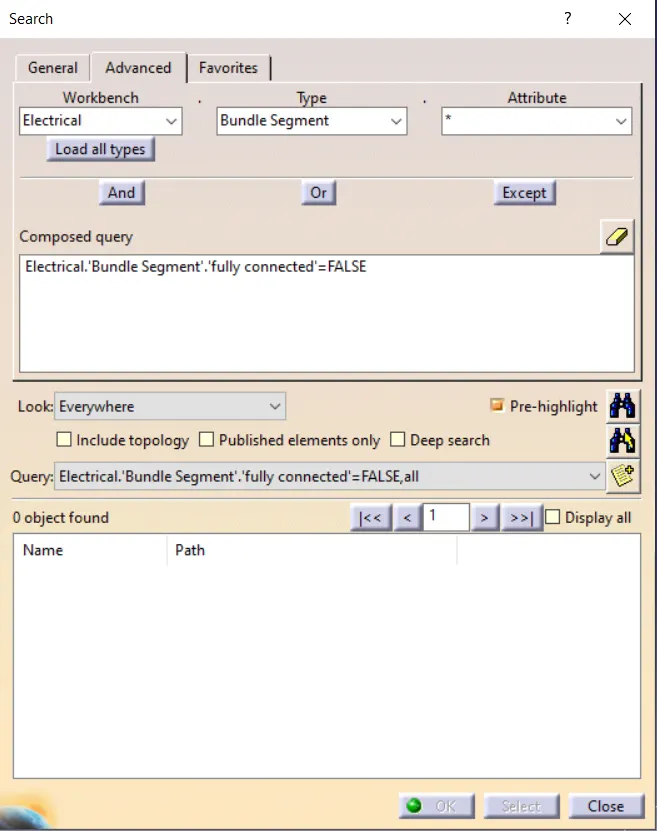
8. Add annotations + No bundle warnings found (snap shown below)
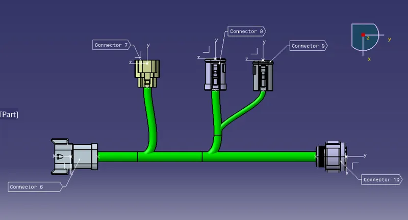
Part 4: - Making assembly of both harnesses and joining them (NOTE: - the connector 5 and 6 are joined electrically even though it will create external reference)
1. Creating a new product file with name Assy_W/H_Context and copying both harness A and B in it.
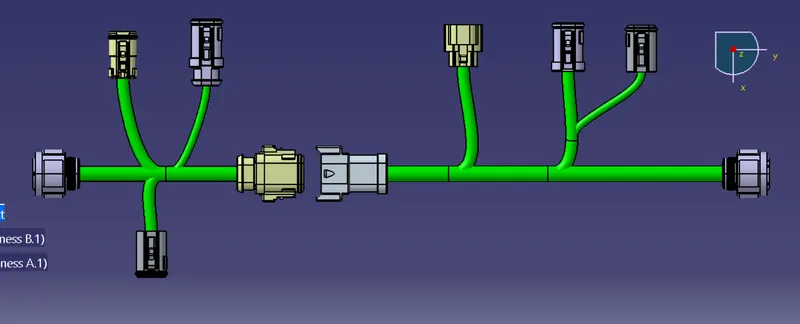
2. Joining connector 5 and 6 electrically using connector connection points in Electrical Design Assembly
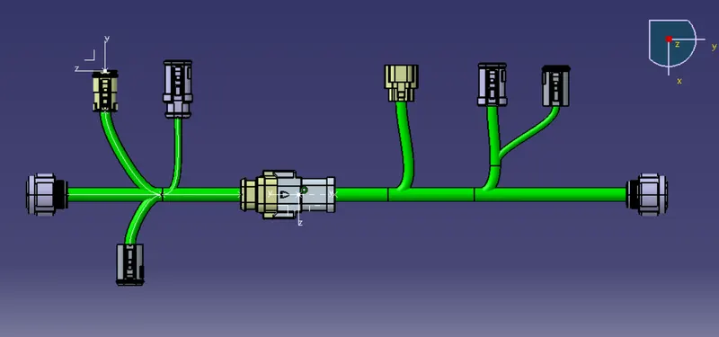
Part 5:- Converting the file into CATPart and saving as IGES