Wiring harness design in CATIA V5 - 3D modeling Week 2 Challenge
Connector - Deutsch DT06 – 08SA
Part 1 - Mechanically Defining the connector: -
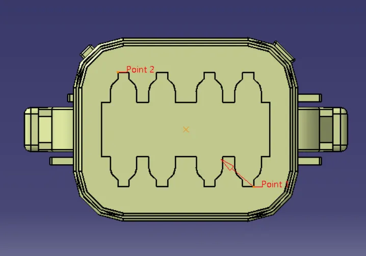
- Definition of Connector Connection Point: - Taking middle of the two points highlighted.
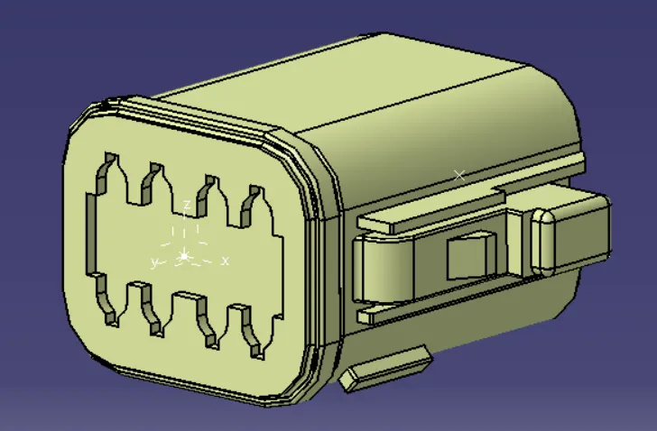
2. Definition of Axis system on the connector connection point: -Defined the axis system on the point defined in previous step. The y axis towards the mating direction, the x axis towards the locking of the connector(either one of the two) and z axis gets aligned automatically.
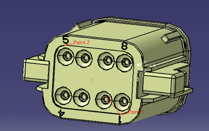
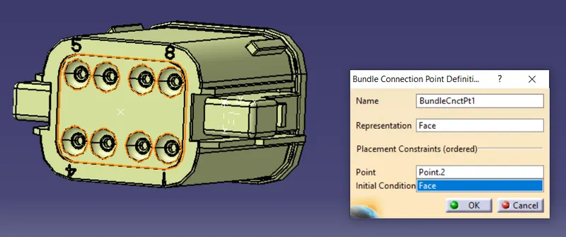
3. Defining the bundle connection point: - Taking middle of the two points highlighted.
Part 2: - Electrically Defining the connector: -
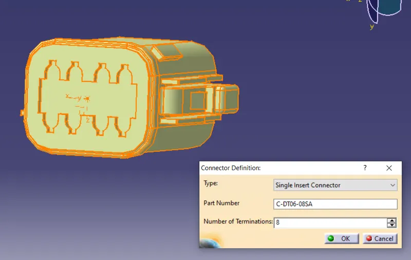
- Defining the part as a connector : - Defined the part electrically as a connector with 8 terminations.
2. Defining the connector connection point: -
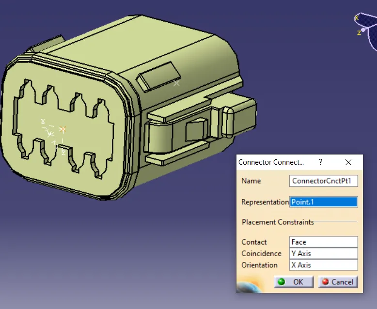
3. Defining the bundle connection point: -
Connector - Tyco 174357-2
Part 1 - Mechanically Defining the connector: -
- Definition of Connector Connection Point: - Taking middle of the two points highlighted.
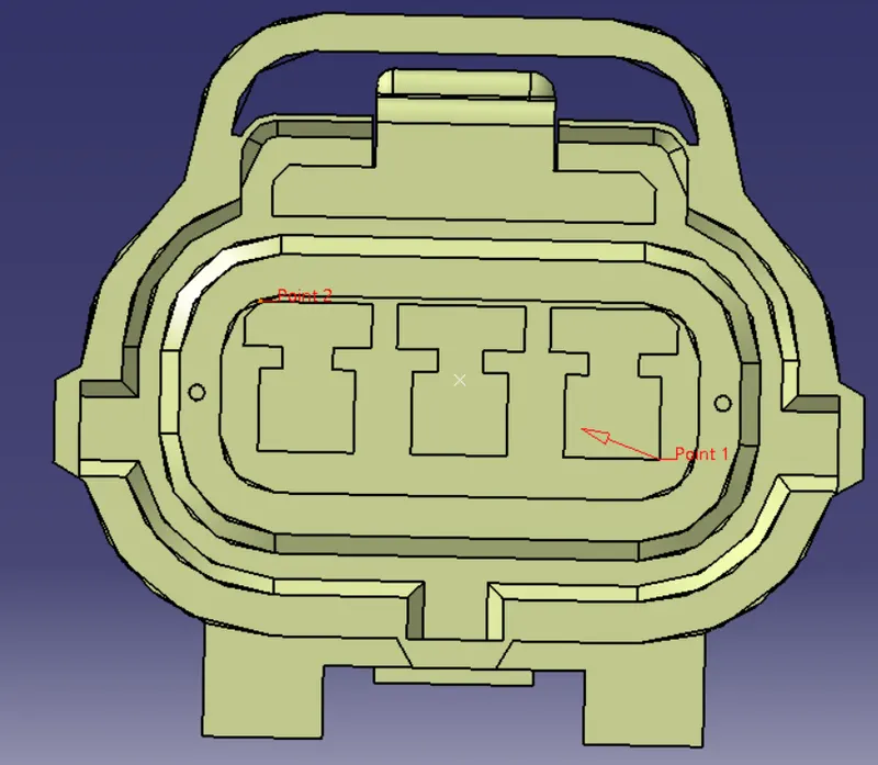
2. Definition of Axis system on the connector connection point: -Defined the axis system on the point defined in previous step. The y axis towards the mating direction, the x axis towards the locking of the connector(either one of the two) and z axis gets aligned automatically.
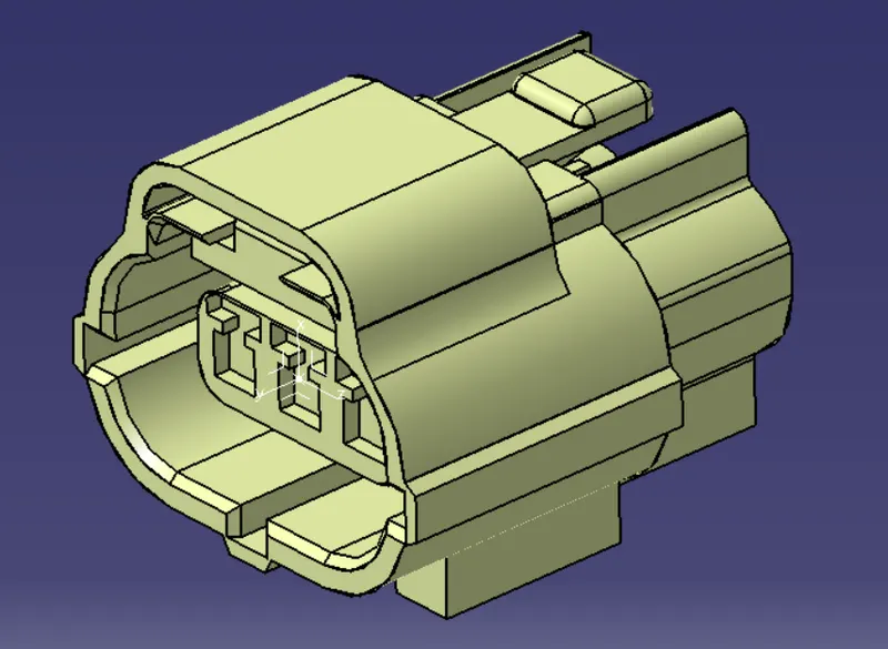
3. Defining the bundle connection point: - Taking center of the circle.
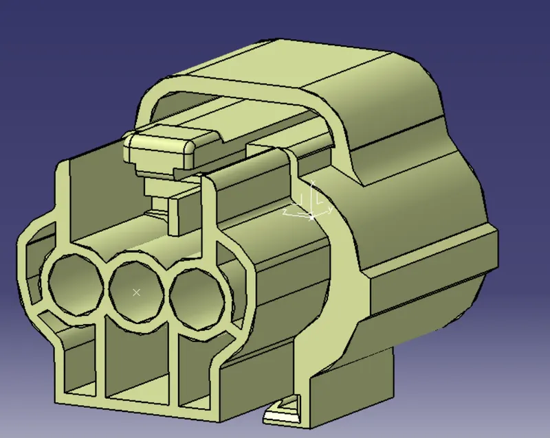
4. Defining the cavity connection point: -
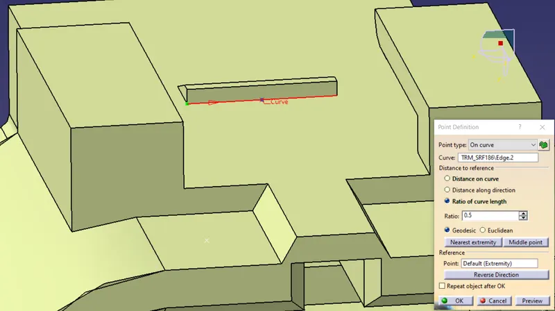
5. Defining the axis system for the cavity connection point: -
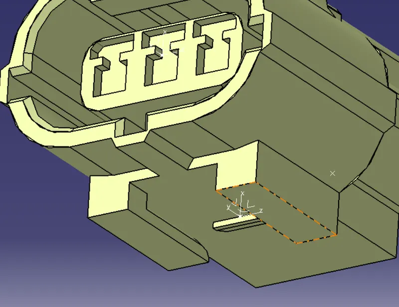
Part 2: - Electrically Defining the connector: -
1. Defining the part as a connector : - Defined the part electrically as a connector with 3 terminations.
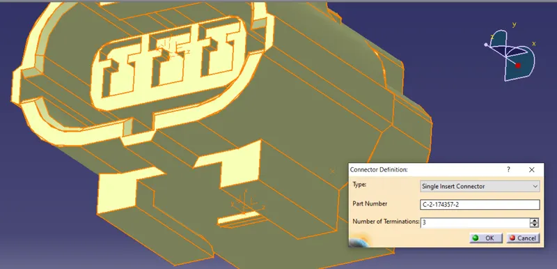
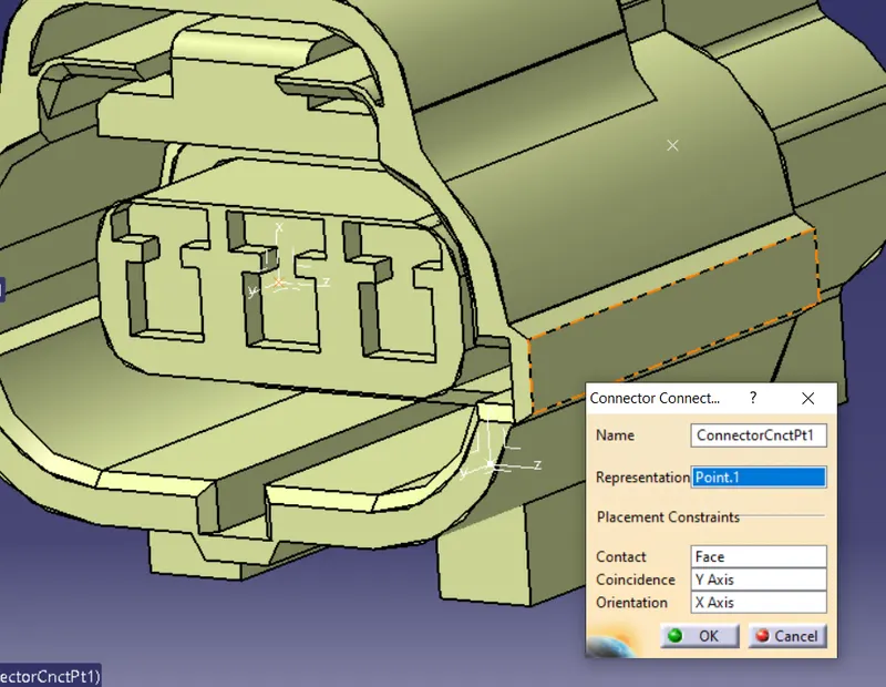
2. Defining the connector connection point: -
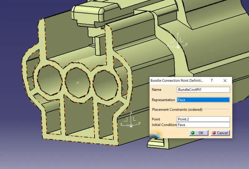
3. Defining the bundle connection point: -
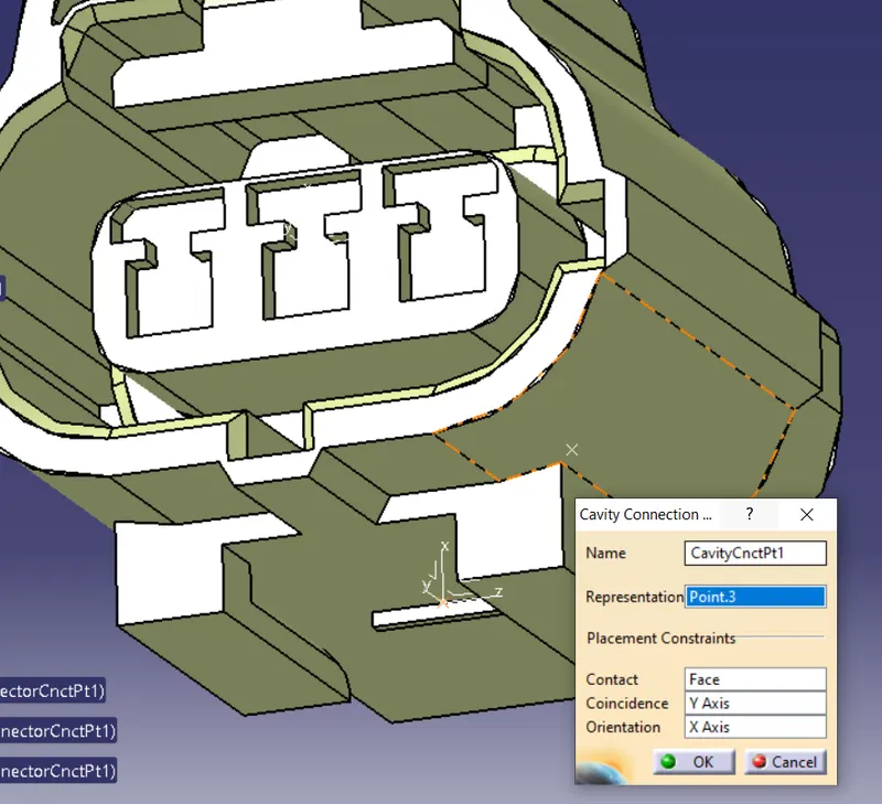
4. Defining the cavity connection point: -
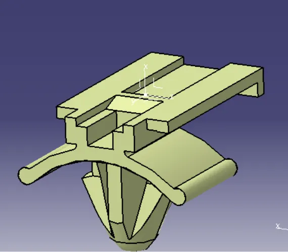
Clip - Tyco 85229-1
Part 1:- Defining the clip Mechanically: -
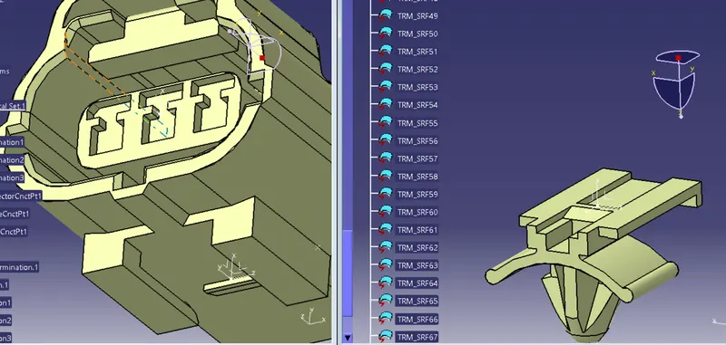
1. Defining the cavity connection point:-
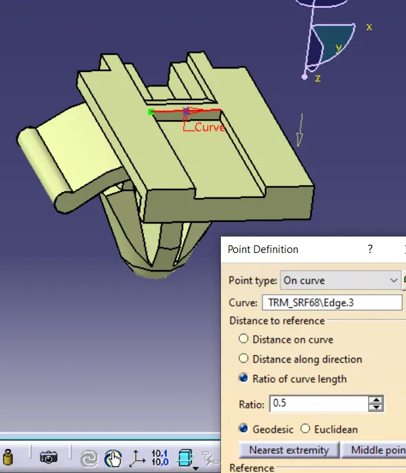
2. Defining the axis system (NOTE: - It is taken into consideration that this clip is mating with connector Tyco 174357-2 and the axis have been defined in accordance to it): -
Part 2: - Defining the clip Electrically: -
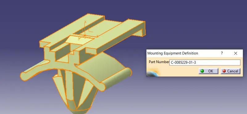
1. Defining part as mounting equipement: -
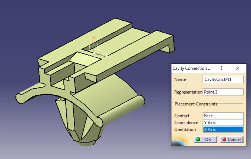
2. Defining cavity connection point: -
Catalogue Creation: -
1. Creating a new catalogue file
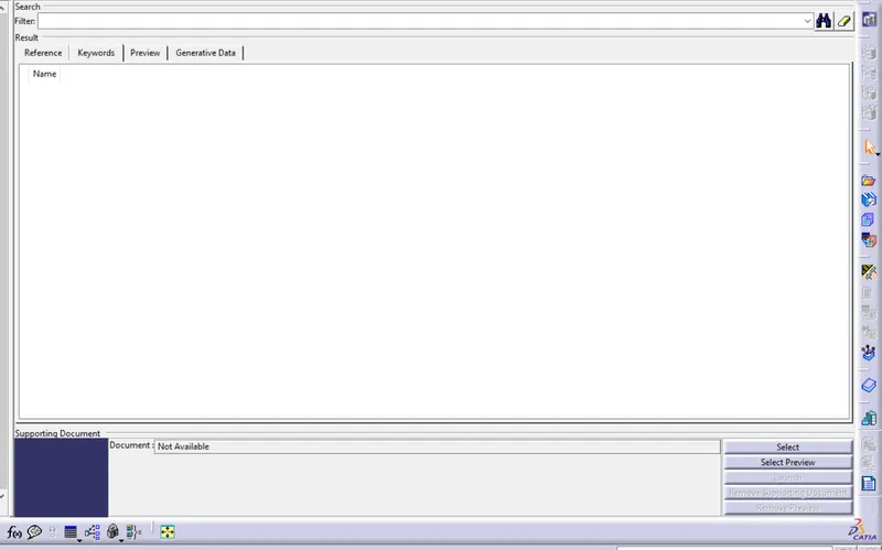
2. Adding a new family as a standard catalogue
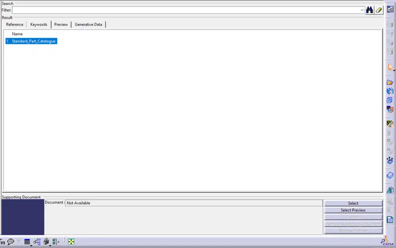
3. Storing every part in catalogue family: -
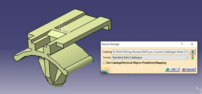
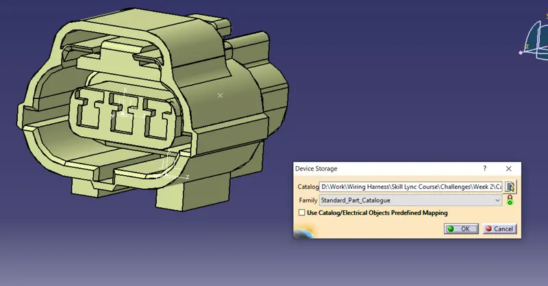
NOTE- All parts are commonly saved in one single family as Standard_Part_Catalogue. No division of family is done according to part type i.e. connectors and clips due to less quantity.