Wiring harness design in CATIA V5 - 3D modeling Week 5 & 6 Challenge
AIM- Route two electrical harnesses as per the given layout and interconnect them as a single harness assembly and then check for bundle continuity, bundle warnings, and then give annotations to the final harness assembly.
OBJECTIVE-
- The objective of this project is to first route the two Harness A and Harness B as per the given harness layout.

Figure 1: Shows the layout of two Harness 1(A) and Harness (2)
The electrical connectors are represented by numbers in the above figure. There are 8 different types of connectors at 10 different locations.
- Bundle continuity has to be checked for the two created harness.
- After the two Harnesses are created, the next objective is to have them interconnected electrically.
- Check for bundle warnings in Harness 1 and Harness 2.
- Add annotations to all the connectors in Harness 1 and Harness 2.
- The final objective of this project is to convert the final harness file into IGS file format.
CONTENT-
The following steps are to be done to complete this project.
STEP 1-Define all the electrical connectors geometrically and electrically so that they can be used in the wiring harness
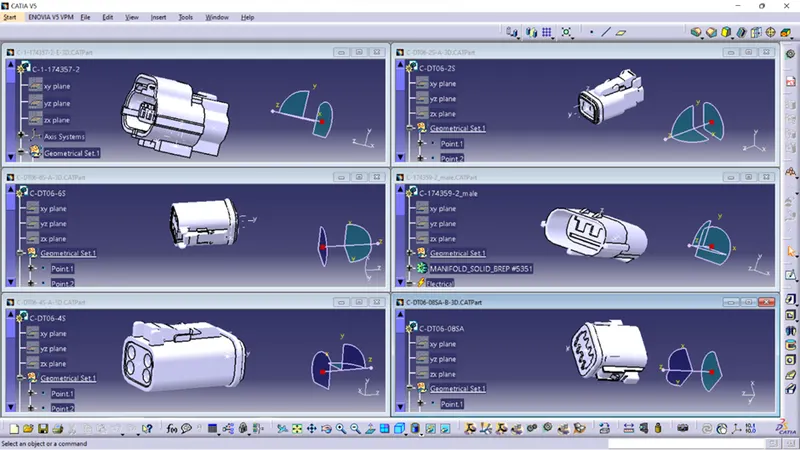
STEP 2 (optional)- Create a Base Sketch of both the harness
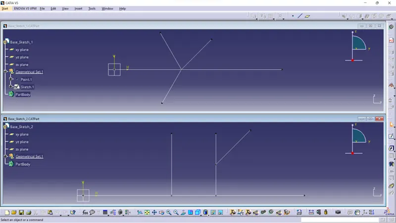
STEP 3- Create harness 1 and harness 2 as shown below by using the electrical harness workbench in CATIA V5.
First, all the connectors are placed at their desired locations. Second, bundle segments are created between the connectors with branch points and branches as shown below.
Bundle diameter is assumed to be 15mm and 10mm for different bundle segments. Bend ratio is given as 1.5 and slack is given as 0% for all the bundle segments.
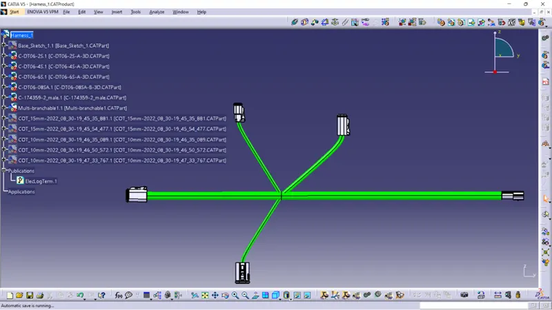
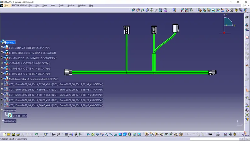
STEP 4- After Harness 1 and Harness 2 are created the next step is to check the bundle continuity.
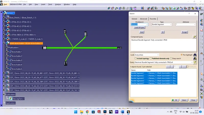
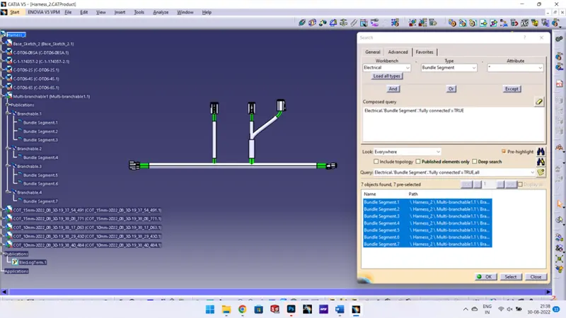
First, we have to make sure multi-branchable is selected and then we have to go in Edit>Search>Advanced>Electrical Workbench>Type-Bundle Segment>Attribute-Fully Connected.
Selecting the "TRUE" option will show all the connected bundle segments while selecting the "FALSE" option will show all the non-connected bundle-segments.
For now, we will select the "TRUE" option and search for results. All the bundle segments in Harness 1 and Harness 2 will be displayed showing that there is bundle continuity in Harness 1 and Harness 2.
STEP 5- In this step, we have to interconnect the Wiring Harness 1 and Harness 2 electrically. There are a few steps that have to be followed to connect the two harnesses electrically.
First, make a new product file in CATIA and rename it as " Harness 1 and Harness 2 ".
Second, copy both harness A and harness B and paste it into the newly created product file to make the final harness assembly.
Third, at this stage, we can use manipulation tools found in the assembly design workbench in CATIA V5 to connect the two-wiring harness. But one should remember that by following this process the two harnesses will not be connected electrically. To properly connect them we have to go to Electrical Assembly Design workbench and use "connect electrical devices" feature.
Fourth, once we are inside the electrical assembly design workbench, we should electrically connect the male and female connectors as shown below.
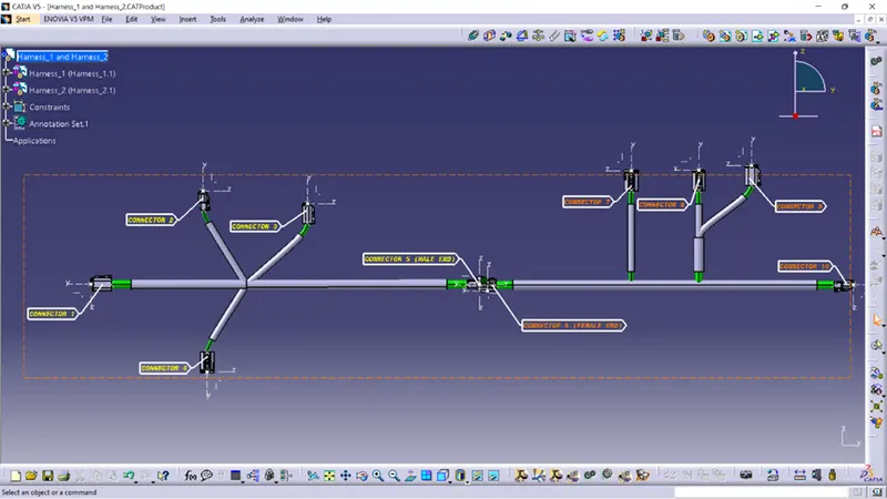
First, we have to choose a plane on which the annotation will be placed. Here we will be choosing the front plane as shown below for Harness 1 and Harness 2. We should make sure that the geometrical bundle is active before choosing the annotation plane.
Second, select "flag note with ladder" function and then click on connectors individually. Give the necessary information to all the connectors.
After annotations are added to all the connectors, we should change the annotation font size and colour so they are easily visible.
STEP 6- In this last step we have to convert out Final Harness Assembly file into IGS format. In order to do this, we should follow the steps as shown below.
Mechanical Assembly Workbench>Tools>Generate CAT Part from product
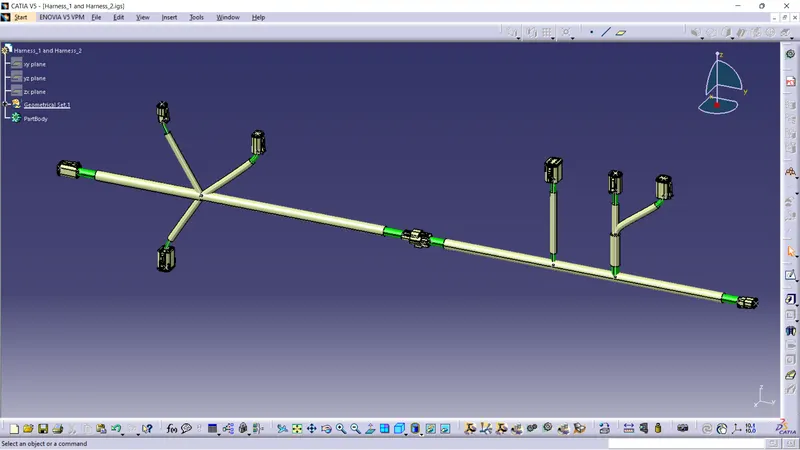
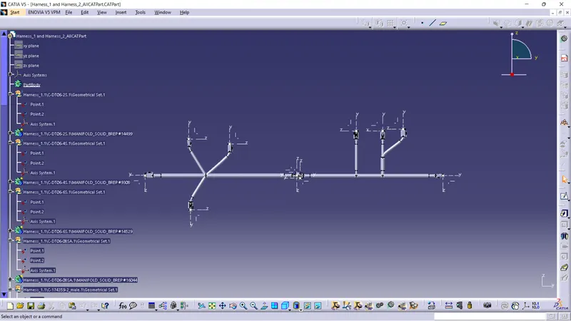
Once the CAT part is created the whole product file is converted into a single part. At this stage, it can be noticed that all the bundle segments are grey in colour. So, we will go back and add green colour to each bundle segment so that they look same as the Final Harness Assembly.
CONCLUSION- Routing of the two electrical harnesses as per the given layout was achieved and interconnection between them as a single harness assembly was established. Both the harness were checked and corrected for bundle warnings and bundle continuity. At the very end, annotations were added to all the connectors and the final harness assembly file was converted into IGS format.