Radar Mast & Final Assembly of Yacht
MODELLING, ASSEMBLING AND RENDERING OF SUNSEEKER PREDATOR YACHT
Objective:
The main objective is to produce a detailed model of different parts of yacht with the help of blue prints and some given dimensions and assembling the entire model.
Introduction:
- Solidworks software is a mechanical cad software which helps the designers to show their idea of a part or model in a realistic view in a virtual representation without actually producing a real part, which is so helpful to make corrections or to make new changes in the model easily before making a physical part product.
- In the process of modelling a sunseeker predator yacht we design a part or model by using initial 2D sketches, and then we turn them into 3d models using the tools like surface tools, featuring tools etc.
- Assembling and visualization plays an important role in any model that we create in a cad software.
- Here almost 90% of the model is modelled using surface modelling and the we make them into a solid body.
- Most of the part bodies are modelled using blue prints only.
DESIGN METHODOLOGY:
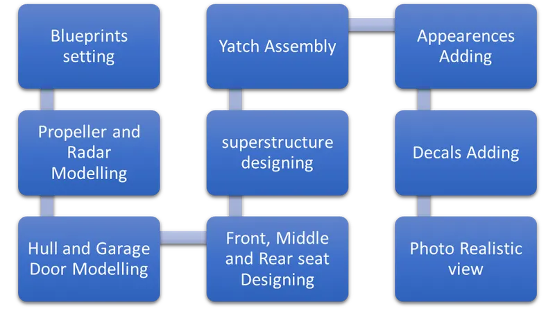
TYPES OF COMMANDS:
Sketch:
- Create the sketches and decide how to dimension and where to apply relations.
Features:
- Select the appropriate features, such as extrudes and fillets, determine the best features to apply, and in what order to apply those features must be decided.
Surfaces:
- Surfaces are a type of geometry that can be used to create solid features.
Assembly
- Select the components to mate and apply the mates.
TYPES OF SKETCHES:
- 2-D SKETCH:
Creating a model usually begins with a sketch. From the sketch, we can create features. We can combine one or more features to make a part. Then, we can combine and mate the appropriate parts to create an assembly. From the parts or assemblies, we can then create drawings.
- 3-D SKETCH:
When sketching in 3D, we can snap to the major directions, X, Y, or Z, and constraints are applied Along X, Y, Z respectively. These are constraints to the global coordinate system.
When sketching on a plane, we can snap to the horizontal or vertical directions in the plane, and constraints are applied to the Horizontal and the Vertical. These are constraints to a plane, planar face, etc.
SKETCH COMMANDS:
Smart Dimension - Creates a dimension for a selected sketch entity.
Line - Line is one of the first sketching tools in Solid works Sketch Command Manager which can be drawn horizontally, vertically or at any angle. It plays very important role to complete the 2D drawing of the product or part and very easy to utilize its features.
Circle - The circle is another important sketching tool which enables to create the circular drawing on the graphics area.
Rectangle - Sketches rectangles or square with a centre point at a selected angle.
Spline - A 2D or 3D curves defined by a set of control points. Points within a spline can be added or deleted.
Sketch Fillet - A tangent arc in between two sketch entities can be created.
Point - Inserts a point or vertex into a sketch entity. This cannot be deleted if it is part of sketch endpoint or centre point.
Convert Entities - Convert Entities enables you to copy model edges into your active sketch. These sketch elements are automatically fully defined and constrained with an On Edge relation. Convert Entities is like Offset Entities except that the offset distance is always zero.
Text - It can be used to write the text necessary wherever required either it's a plane or face.
Offset Entities - Copy a sketch entity to a specified distance from the original entity. Must have a sketch entity already drawn and selected to use this tool.
Sketch Picture - Insert an image file into the background of a sketch. This allows the user to 2D sketches based off of the image. Use the sketch picture property manager to alter the inserted image.
- FEATURES:
Some sketch-based features are shapes such as bosses, cuts, and holes. Other sketch-based features such as lofts and sweeps use a profile along a path. Another type of feature is called an applied feature, which does not require a sketch. Applied features include fillets, chamfers, or shells. Typically, we create parts by including sketch-based features such as bosses and holes. Then we add applied features. It is possible to create a part without sketch-based features.
FEATURE COMMANDS:
Extruded Boss/Base - An Extruded Boss/Base feature will allow us to take a 2D sketch and add thickness to it in the third dimension.
Extruded Cut - It's a tool to remove material by projecting a sketched section normal to the sketching plane.
Split - Lines are used to divide model faces into two. Split lines are created like any other sketched feature.
Dome - It can add one or more domes to the selected planar or non-planar faces. The software calculates the distance using the radius of the arc as a basis for the dome.
Pierce Relationships - The Pierce relationship is used in sweeps. It can be thought of as a 3D Coincident relationship.
Project Curve - Select Bi-directional to create a projection that extends on both sides of the sketch. The curve can be used as a path for a sweep.
Composite Curve - We can create composite curves by combining curves, sketch geometry, and model edges into a single curve. Composite curve can be used as a guide curve when creating a loft or a sweep.
- SURFACE MODELLING:
Surface modelling is a method of creating planar or non-planar complex geometry which has zero thickness. Zero thickness geometry is known as surface.
SURFACE COMMANDS:
Lofted Surfaces — Creates a lofted surface between two or more profiles or sketches. Specify start and end constraints and add guide curves to control the path shape.
Boundary Surfaces - The boundary surface feature lets us to create surfaces that can be tangent or curvature continuous in both directions.
Extruded Surfaces — Extrudes a sketch or selected sketch contours in one or two directions two create a surface feature.
Revolved Surfaces — Revolves a sketch or selected sketch contours around an axis to create a surface feature.
Swept Surfaces — It Sweeps a closed profile along an open or closed path to create a surface feature.
Filled Surfaces — Patches a surface within a boundary defined by edges, sketches, or curves. We can use constraint curves to fill surfaces and adjust resolution control to improve surface finish.
Ruled Surfaces — Inserts ruled surfaces in a specified direction from edges. Tangent to surface, Normal to surface, tapered to vector, perpendicular to vector or sweep can be selected.
Trim Surface — It trims the surfaces where a surface intersects with another surface, a plane or a sketch
Knit Surface — It combines two or more adjacent, non-intersecting surfaces into a single surface body. The surfaces must joint at an edge. If the resulting knit surface encloses a volume, we can create a solid body from the Property Manager
Move/copy surfaces — Moves or copy surfaces about a plane or a sketch.
Offset Surface — This tool helps us to create an offset surface with gaps.
Extend Surface — Extends one or more edges or faces on a surface, based on end conditions and extension type.
Mirror surfaces — A mirror feature is a copy of a selected feature, mirrored about a plane or planar face. A mirror sketch entity is a copy of a selected sketch entity that is mirrored about a centreline.
Reference plane — We can create planes in part or assembly documents. We can use planes to sketch, to create a section view of a model, for a neutral plane in a draft feature, and so on.
Projected curve — A projected curve is typically used either in sweeps and lofts as path or guide curve. There are two types of projected curves:
Sketch on Sketch: Use two sketches to make a single curve.
Sketch on surface: Use a sketch to project on a surface.
Split line — The Split Line tool projects an entity (sketch, solid, surface, face, plane, or surface spline) to surfaces, or curved or planar faces. It divides a selected face into multiple separate faces.
Split point — We can split a sketch entity to create two sketch entities.
Fillet - A fillet is an internal rounding of a corner or edge in a sketch, or an edge on a surface.
PART MODELLING DESCRIPTION:
- BLUE-PRINT SETUP:
A blueprint is a reproduction of a technical drawing or engineering drawing using a contact print process on light sensitive sheets. A blueprint is a guide for making something, it's a design or pattern that can be followed. They were easier to read and faster to make.
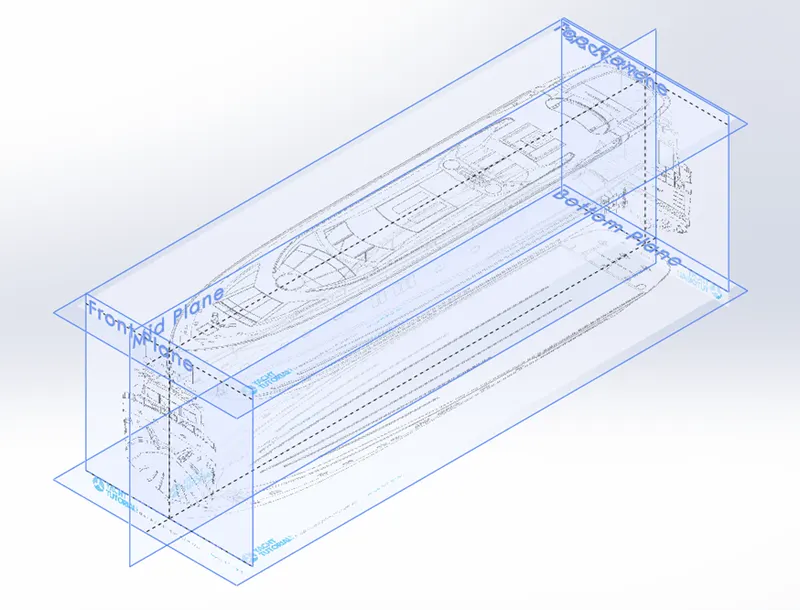
The above shown Blueprint was used to model the Yacht in a fully defined constraint. For setting up the Blueprint the Sketch pictures options were used and placed the different blueprints at the required planes.
- PROPELLER:
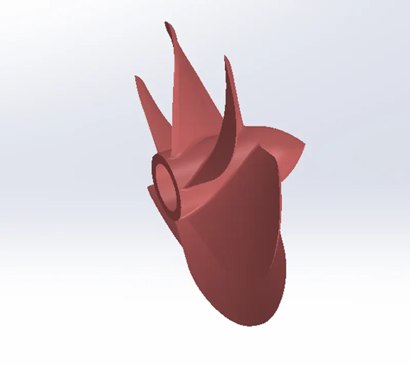
There can be three propellers. It is the most important part of the ship without which a ship can't move. So, the main function of propeller is to propel the ship in the forward direction by producing thrust on water. Its working principles are Newton's third law of motion and Bernoulli's theorem.
COMMANDS USED TO MODEL
In Sketch
- Spline
- Circle
- Line
In Features
- Revolved Boss/Base
- Lofted Boss/Base
- Extruded Cut
- Reference Plane
- Circular Pattern
- Fillet
- RADAR:
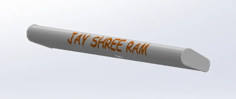
Marine radars are X band or S band radars on ships, used to detect other ships and land obstacles, to provide bearing and distance for collision avoidance and navigation at sea. They are electronic navigation instruments that use a rotating antenna to sweep a narrow beam of microwaves around the water surface surrounding the ship to the horizon, detecting targets by microwaves reflected from them, generating a picture of the ship's surroundings on a display screen.
COMMANDS USED TO MODEL
In Sketch
- Spline
- Text
- Circle
- Line
In Features
- Extruded Boss/Base
- Extruded Cut
- Sketch Pattern
- Fillet
- Mirror
- Split Line
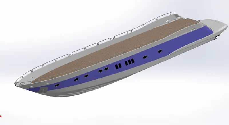
- HULL:
A hull is the watertight body of a ship or boat. The hull may open at the top or it may be fully or partially covered with a deck. The line where the hull meets the water surface is called the waterline. The hull of a ship is the most notable structural entity of the ship. The hull is a watertight body of a vessel which may be open or may be partially covered with a deck.
COMMANDS USED TO MODEL
In Sketch
- In Sketch
- Line
- Spline
- Circle
- Rectangle
- Arc
- Slot
- 3D Sketch
- Sketch picture
In Surfaces
- Extruded Surface
- Revolved Surface
- Lofted Surface
- Surface Trim
- Surface Fill
- Surface Knit
- Delete Face
In Features
- Project Curve
- Chamfer
- Fillets
- Reference Plane
- Split
- Split Line
- Extruded Boss/Base
- Extruded Cut
- Mirror
- GARAGE DOOR:
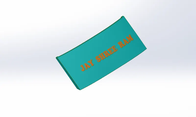
A garage door is a large door on a garage that opens either manually or by an electric motor. Garage doors are frequently large enough to accommodate automobiles and other vehicles. Doors are made of wood, metal, or fiberglass, and may be insulated to prevent heat loss.
COMMANDS USED TO MODEL
In Sketch
- Line
- Spline
- Circle
- Text
In Features
- Fillet
- Reference Plane
- Shell
- Extruded Cut
- Mirror
- SUPERSTRUCTURE:
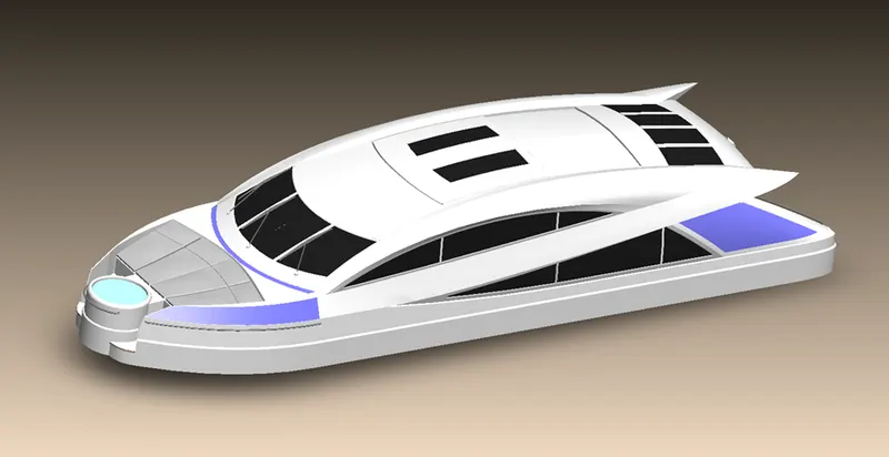
A superstructure is an upward extension of an existing structure above a baseline called ground level and it usually serves the purpose of the structure's intended use. A superstructure is a decked structure on the freeboard deck, extending from side to side of the ship.
COMMANDS USED TO MODEL
In Sketch
- In Sketch
- Sketch Picture
- 3D Sketch
- Line
- Spline
- Circle
- Rectangle
- Centre Point Arc
In Surfaces
- Extruded Surface
- Swept Surface
- Ruled Surface
- Knit Surface
- Trim Surface
- Extend Surface
- Filled Surface
- Lofted Surface
- Revolved Surface
- Fillet
- Chamfer
In Features
- Project Curve
- Reference Curve
- Convert Entities
- Split
- Split Line
- FRONT SEAT:
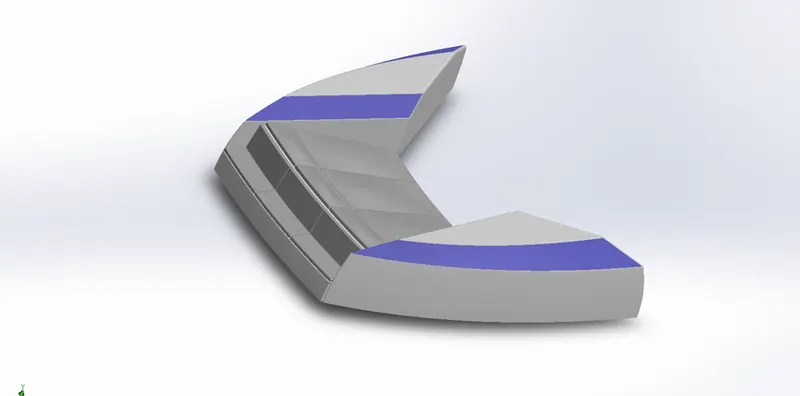
Front seats feature two connected seats that are built back to-back from one and other. They have a built-in storage unit underneath them. Lounge seats can also fully recline right back to make it easier for you to kick your feet up and get more comfortable. The front seat in our model was placed before the superstructure and also it has sun pads to rest on it.
COMMANDS USED TO MODEL
In Sketch
- Sketch Picture
- Line
- Spline
- Circle
- Arcs
In Surfaces
- Extruded Surface
- Swept Surface
- Knit Surface
- Trim Surface
- Filled Surface
- Lofted Surface
- Revolved Surface
In Features
- Fillet
- Chamfer
- Extruded Cut
- Revolved Boss/Base
- Mirror
- Dome
- MIDDLE SEAT:
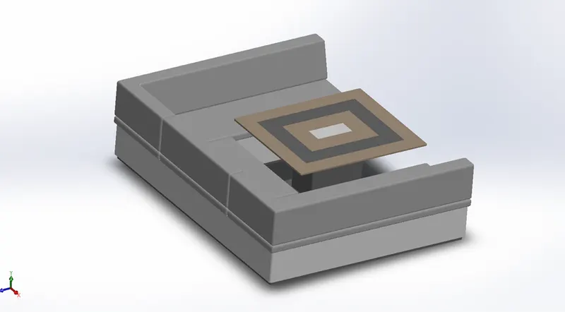
The middle seat in our model was placed just behind the superstructure. It is provided with a luxury table to dine out. It can also be used to have casual meetings with co-passengers.
COMMANDS USED TO MODEL
In Sketch
- Sketch Picture
- Line
- Rectangle
In Features
- Extruded Boss/Base
- Chamfer
- Fillet
- Mirror
- Reference Plane
- REAR SEAT:
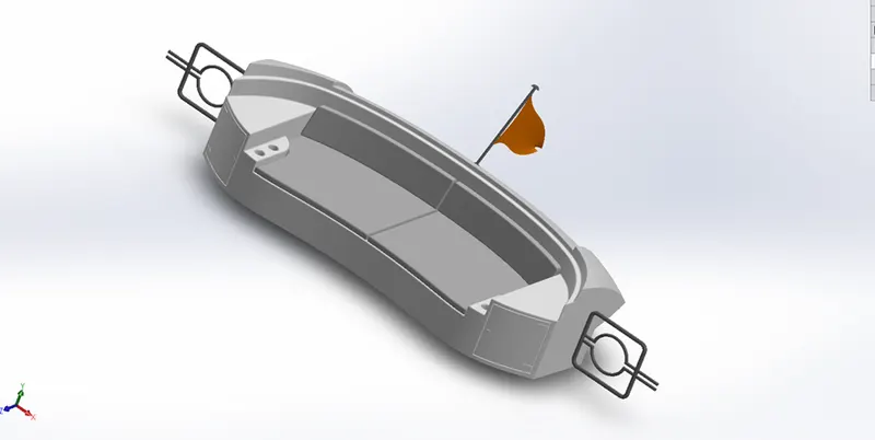
The rear seat was placed at the end of the deck surface. The rear seat consists of locker racks and steel doors for our stairs. The flag was also placed behind the rear seat since it's the end part of our yacht. To have a nice view from the yacht while having a drink the rear seat was also provided with a slot to rest the glass or mug.
COMMANDS USED TO MODEL
In Sketch
- Sketch Picture
- Line
- Spline
- Circle
- Arcs
- Rectangle
In Surfaces
- Extruded Surface
- Swept Surface
- Off-Set Surface
- Knit Surface
- Filled Surface
- Lofted Surface
- Ruled Surface
In Features
- Fillet
- Chamfer
- Extruded Boss/Base
- Revolved Boss/Base
- Reference Plane
- Mirror
- RADAR MAST:
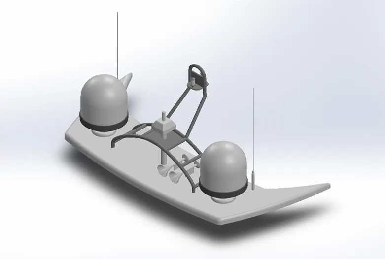
A mast is a vertical ship structure mounted on top of bridge and forward of the forecastle towards the ship's bow. It accounts for the support platform for the ships derrick and hold necessary equipment's such as radars, navigation light and ships horn in case of foremast. They are made of high tensile steel with added rigidity based on the size of derricks it holds. Other than that, a ships main mast is also used to hoist ships flag.
Out of different parts of ship the main job of mast is to hold necessary equipment such as radar receiver, navigation lights, ships horn, flags and derricks in some case.
COMMANDS USED TO MODEL
In Sketch
- Sketch Picture
- Line
- Spline
- Rectangle
- Arcs
In Features
- Extruded Boss/Base
- Lofted Boss/Base
- Revolved Boss/Base
- Swept Boss/Base
- Reference Plane
- Projected Curve
- Fillet
- Mirror
- Dome
- Shell
- ASSEMBLY:
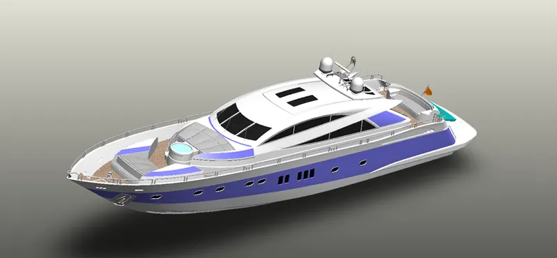
An assembly is a document in which parts, features, and other assemblies are mated together. The parts and subassemblies exist in documents separate from the assembly. For example, in an assembly, a piston can be mated to other parts, such as a connecting rod or cylinder. This new assembly can then be used as a sub assembly in an assembly of an engine. The extension for a SolidWorks assembly file name is SLDASM.
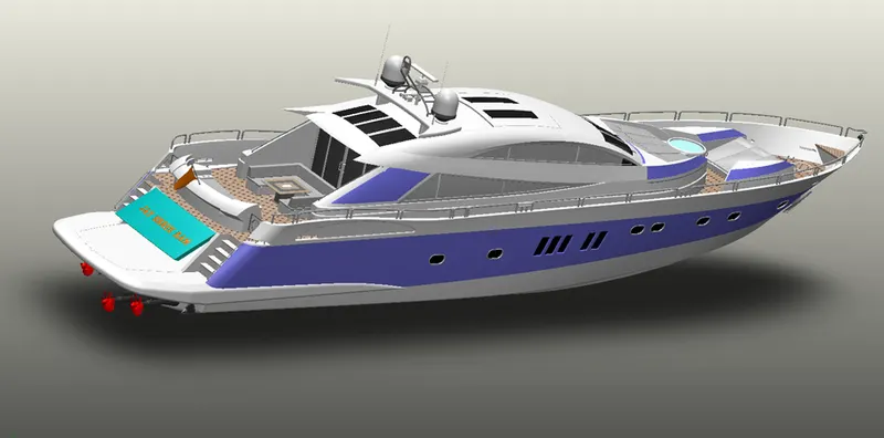
ASSEMBLY COMMANDS:
- Smart Mate - A Smart mate is an assembly mating relation that is created automatically.
- Mate - A mate is a geometric relationship, such as coincident, perpendicular, tangent, and so on, between parts in an assembly.
- Mate group - A mate group is a collection of mates that are solved together. The order in which the mates appear within the mate group does not matter.
- Sub Assembly - A sub assembly is an assembly document that is part of a larger assembly. For example, the steering mechanism of a car is a subassembly of the car.
- Insert Components - We can insert multiple instances of the group of components without closing the Property Manager.
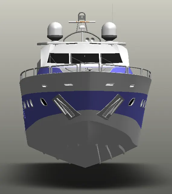
FRONT VIEW OF YACHT:
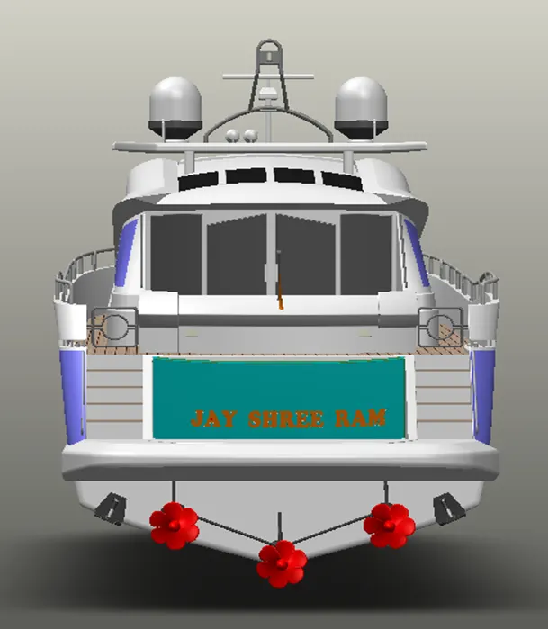
REAR VIEW OF YACHT:
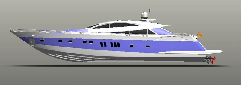
SIDE VIEW OF YACHT:
- RENDERING:
Rendering of the Solidworks model is done using PhotoView 360
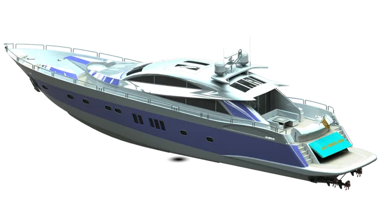
PHOTO VIEW 360:
PhotoView 360 is distinguished from Real View in that it is not a process of the GPIJ, and photorealistic renderings can be achieved regardless of the graphics card used. This is because it is entirely calculated on the CPU on your PC and is rendered in a sequential event and is therefore not dynamic. PhotoView 360 renderings are more photorealistic than Real View because light rays and reflections are more accurately calculated.
PhotoView 360 rendering supports
- Self-reflection (reflection of objects in one another)
- HDRI (environmental) lighting.
Appearances:
Appearances control the way the surfaces of the model look. They can be applied at the assembly, part, body, feature or face of a model All surface of a model have an appearance applied to them.
Lighting:
Lights may be added in the same way a photographer adds lights when taking photographs. PhotoView 360 uses the same lights as SolidWorks but also uses lighting from the rendering environment or scene PhotoView 360 has the sophistication to trace light rays and reflections.
Decals
Images, such as company logos, can be applied to models.
Output
The rendered output from PhotoView 360 can be viewed on the screen, or saved to a graphics file.
Options
PhotoView 360 has its own options. Options allow you to customize the PhotoView 360 settings to reflect your preferences. Options are divided into Output Image Settings, Render Quality Bloom; Contour Rendering and Direct Caustics.
Scenes
PhotoView 360 scenes are made up of the things we see in the rendering that are not the model. They can be thought of as a virtual sphere around the model Scenes are composed of backgrounds, foreground effects, and scenery PhotoView 360 has numerous predefined scenes to make initial renderings quick and easy
CONCLUSION:
By this project I have learned.
- How to design a part or a model with proper 2D sketching and dimensioning.
- How to make a fully defined sketch.
- How to model a part or component using different features like surface modelling and solid modelling etc.
- How to make an assembly by using proper mates.
- How to make a photo realistic view of a model by using photoview360