Wiring harness design in CATIA V5 - 3D modeling Week 5 & 6 Challenge
Q1. Route the following harness layout in Electrical workbench. Make assumption for harness bundle diameters. Use the connectors provided. After completion of routing,
- Check the bundle Continuity. Add snap of result in submission
- Add annotation to all connectors. Make an assumptions for annotations like connect 1 , 2 etc
- Check for the bundle warning. Add snap.
- Generate CAT.part of harness assembly and convert is in. igs format.
Wire Harness Assembly: -
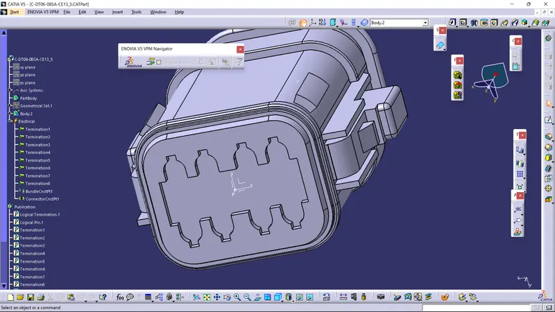
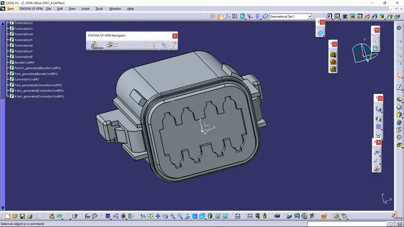
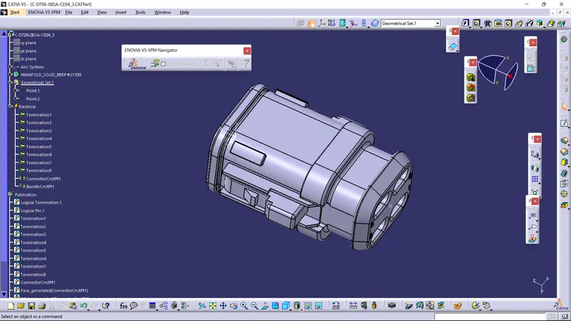
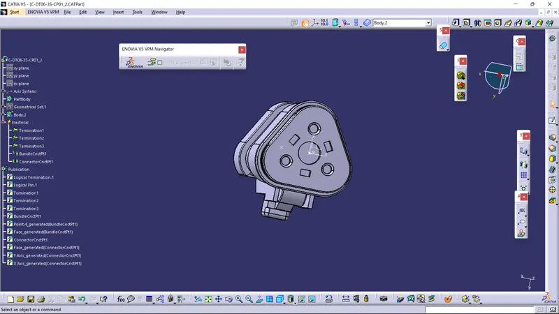
First, we need to define all the downloaded parts as electric components, for that we have to give bundle entry and connector connection point to all the connectors as shown below.
And for this you have to follow the steps which are given below:
- DOWNLOAD THE 3D PART OF THE CONNECTOR
- CREATE REQIRED GEOMETRICAL PARAMETER
- DEFINE PART AS A CONNECTOR
- DEFINE BUNDLE CONNECTION POINT
- DEFINE CONECTOR CONNECTION POINT
- DEFINE CAVITY CONNECTION POINT
Then create a plate and with the help of the given diagram group of lines are drawn on the metal plate in part design workbench as shown below.
NOW CREATE A PRODUCT FILE AND ADD ALL THE CONNECTORS AND PLATE IN THE PRODUCT DESIGN.
Now arrange all the connectors in a similar fashion and by using compass or by using manipulation tools and snap tools.
We have to follow the same process for harness A AND Harness B…..
All photos are mentioned below:
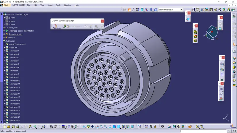
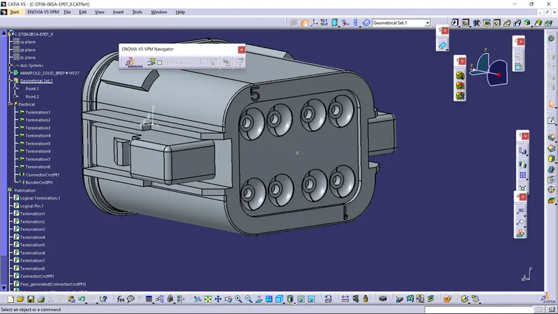
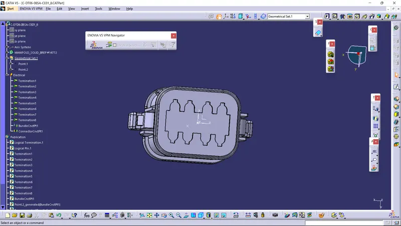
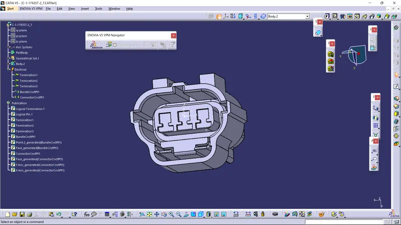
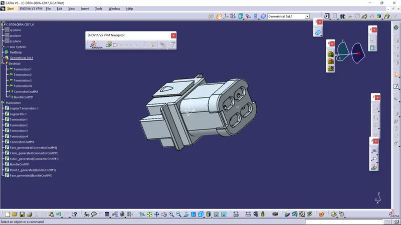
Now the route is defined as required using clicking multi branchable document and then clicking branch definition.
Appropriate diameter is taken and under route definition, the two connectors between which the branch has to be created are
selected and click OK.
Now the branch is created between the connectors as shown below.
And then all the connectors were connected to the specific branch giving proper tangent directions by creating branching points on the main branch as shown in the data.
the protective covering of corrugated tubes was provided on all branches connected to all connectors, Keeping the end extremity at 20mm.
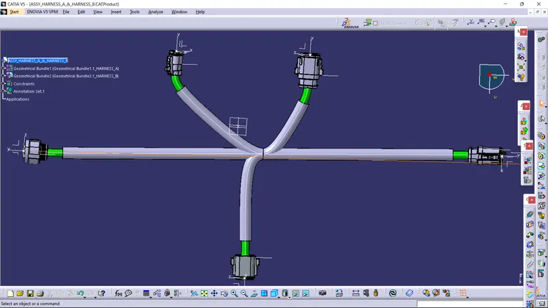
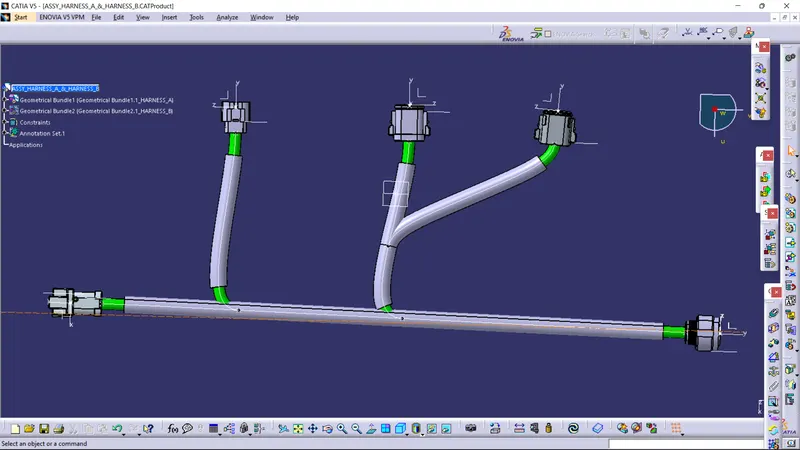
Interconnection of two harnesses: -
In interconnection two harnesses are connected with connector using command ' Connect Elctrical Devices '
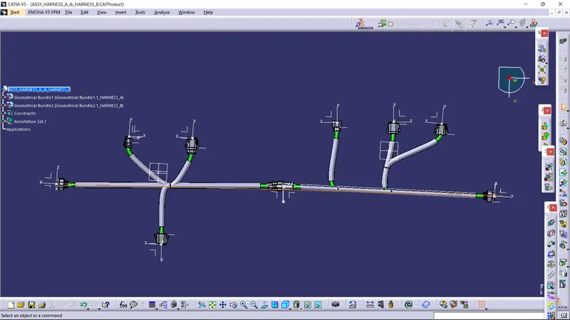
annotation:
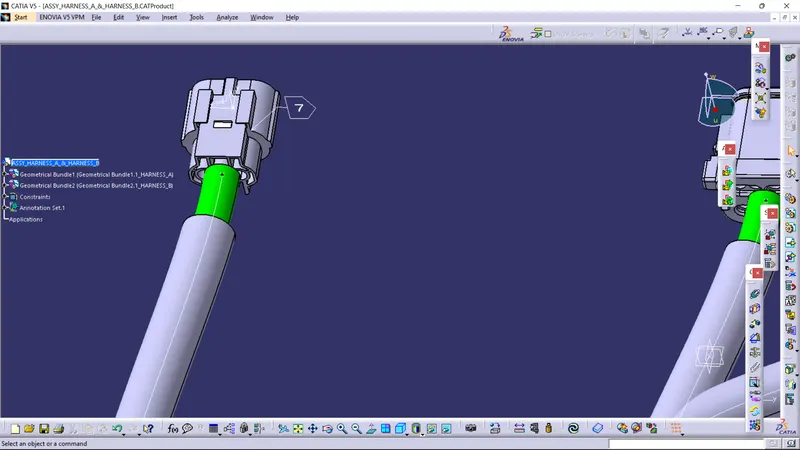
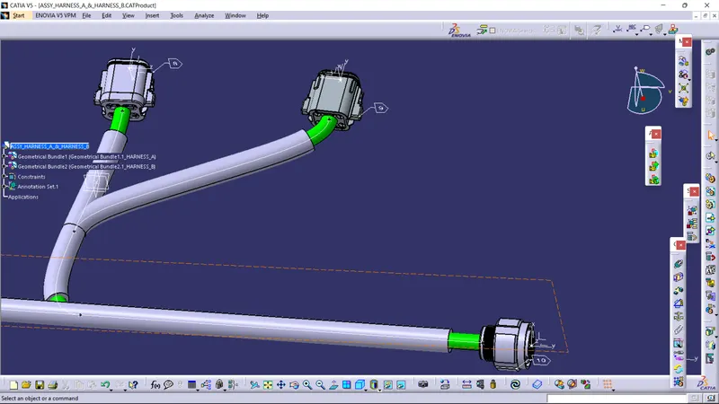
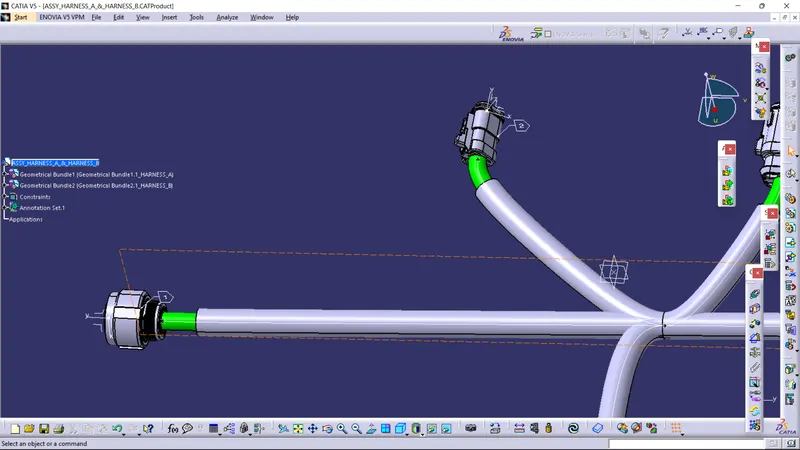
convert the product file into catpart file and then save it as in igs file or in stp file because these file can be open in any cad software.
thankyou